noiseo
- โชว์สินค้าทั้งหมด
- No categories
June 2, 2026
A PCB assembly passes visual inspection. Automated optical inspection finds nothing. Functional test at room temperature is clean. The board ships, gets installed in a vehicle, and three months later starts producing intermittent faults that are difficult to reproduce and expensive to trace.
The cause, when it is eventually found, is ionic contamination. Residual flux activator left on the board surface after soldering, invisible to optical methods and undetectable by functional test under dry conditions, has begun to drive electrochemical corrosion and leakage current in the presence of operating temperature cycling and humidity. The contamination was there from the start. The damage accumulated over time.
Anion and cation testing by ion chromatography is the analytical method that would have found it. This article explains how the test works, what it detects, why it matters specifically for automotive electronics, and how to interpret the results it produces.
What Is Ionic Contamination and Why Does It Matter?
Ionic contamination refers to charged chemical species, either positive ions (cations) or negative ions (anions), present on the surface of an electronic assembly or component. In the context of PCB manufacturing and assembly, ionic contamination originates primarily from flux residues left after soldering. All soldering fluxes contain activators, which are acidic or ionic compounds that break down the metal oxides on solder pads and component leads to allow good solder wetting. After soldering, these activators and their reaction products remain on the board surface as ionic residues.
Under dry conditions, ionic residues are typically benign. They sit on the surface, insoluble in dry air, causing no immediate problem. The failure mode is activated by moisture. When humidity rises or when condensation occurs on the board surface, ionic residues dissolve into a thin electrolytic film. That film becomes a conductive path between adjacent conductors. Current flows where it should not. In the presence of an applied voltage, the ionic species migrate: cations move toward the cathode and anions toward the anode, depositing metal at the cathode in a process called dendritic growth or electromigration. Dendrites are metallic crystalline growths that bridge the gap between conductors, causing intermittent or permanent short circuits.
The ionic species of greatest concern are those that are most mobile, most soluble, and most corrosive: chloride, fluoride, bromide, sulfate, acetate, and formate on the anion side; sodium, potassium, and ammonium on the cation side. Ammonium and organic amines from no-clean flux formulations are particularly significant because they indicate the presence of insufficiently activated or partially decomposed flux residues that retain moisture-absorbing and corrosion-promoting properties.
Ionic contamination is a latent failure mechanism. It is present from the moment of manufacture but causes damage only when activated by humidity and temperature. Testing before shipment is the only reliable way to detect it before it reaches field conditions.
How Ion Chromatography Works
Ion chromatography (IC) is an analytical technique that separates and quantifies ionic species in a liquid sample. The technique was developed in the 1970s and has become the standard method for trace ionic analysis across water quality, food safety, pharmaceutical, and electronics testing applications.
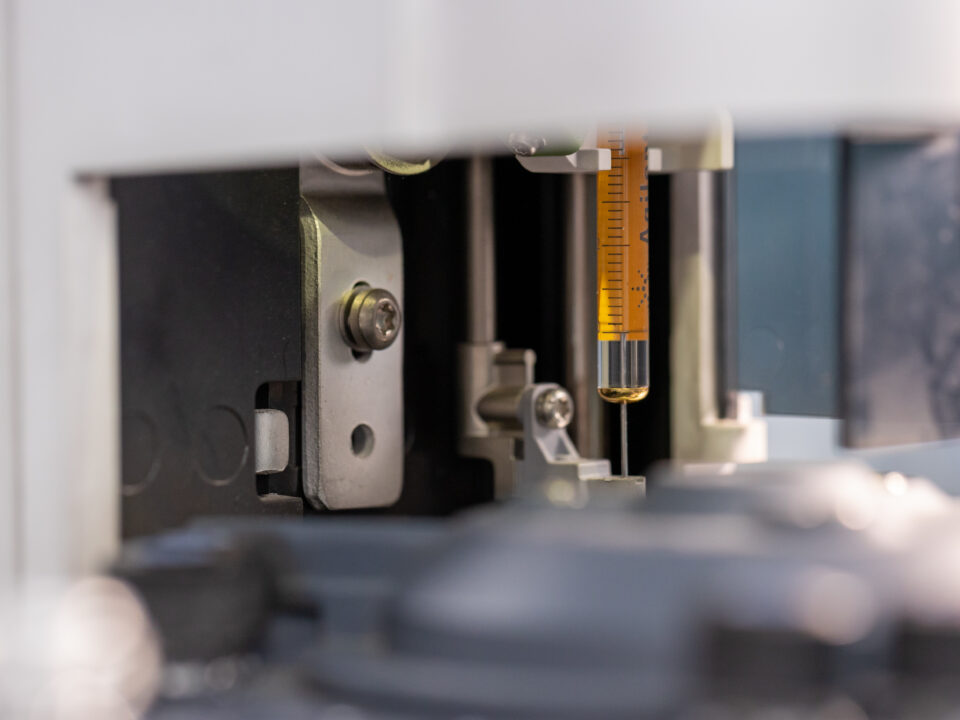
The operating principle is ion exchange chromatography. A liquid sample is injected onto a column packed with a charged stationary phase. Ionic species in the sample are attracted to and retained by the stationary phase, then released sequentially as the mobile phase gradient changes. Because different ions have different affinities for the stationary phase, they travel through the column at different speeds and emerge at the detector at different times, producing a chromatogram with a distinct peak for each ionic species.
Detection in modern IC systems uses a suppressed conductivity detector. As each ionic species elutes from the column, it passes through a suppressor device that converts the mobile phase background ions to low-conductivity water, leaving the analyte ions as the dominant conductivity signal. This suppression step dramatically improves sensitivity and selectivity, allowing detection of ionic species at concentrations of parts per billion (micrograms per litre) in solution, which translates to nanograms per square centimetre on a PCB surface.
Quantification is achieved by comparison with external calibration standards: solutions of known ionic concentration that are run alongside the samples and used to construct a calibration curve for each ionic species. The result for each ion is expressed as the measured concentration in the extract solution, which is then converted to surface density (typically micrograms per square centimetre) using the board surface area extracted.
Anion Analysis vs Cation Analysis
Anion and cation analysis require separate analytical conditions because anions and cations have opposite charges and require stationary phases and mobile phases of opposite polarity for effective separation. In practice, most IC instruments configured for anion analysis use an anion exchange column with a carbonate or hydroxide mobile phase, while cation analysis uses a cation exchange column with a dilute acid mobile phase.
The two analyses can be conducted sequentially on the same instrument platform or simultaneously on a dual-channel instrument. For a comprehensive ionic contamination assessment, both anion and cation analysis should be conducted from the same extraction solution, providing a complete profile of all ionic species present.
The Standard Method IPC-TM-650 2.3.28
The primary standard governing ionic contamination testing of PCBs and electronic assemblies by ion chromatography is IPC-TM-650 Method 2.3.28, published by IPC (the Association Connecting Electronics Industries). This method defines the extraction procedure, the IC analytical conditions, and the reporting requirements for ionic contamination testing.
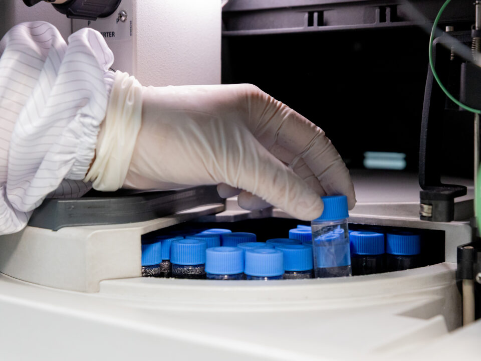
The extraction procedure in IPC-TM-650 2.3.28 uses a mixture of 75 percent isopropyl alcohol and 25 percent deionised water (the IPA-water extract). The board or assembly is placed in a clean vessel and covered with a defined volume of the extraction solvent. The extraction is conducted for one hour at 80 degrees Celsius under agitation. The extract is then filtered and injected into the IC system for anion and cation analysis.
The extraction is designed to dissolve ionic species from the board surface into the solvent, including flux residues that are not fully soluble in water alone. The IPA component improves dissolution of organic flux residues while the water component provides the ionic medium for dissolution of inorganic ionic contaminants. The result is an extract that captures the full range of ionic species relevant to electronics reliability assessment.
Ionic Species
Ion Type
Primary Source on PCB
Failure Risk
Chloride (Cl-)
Anion
Flux activator residue, environmental deposition, halogenated materials
High – aggressive corrosion initiator, highly mobile
Fluoride (F-)
Anion
Some flux formulations, etching process residues
Moderate to high – corrosive to aluminium and some metals
Bromide (Br-)
Anion
Flame retardant materials, some flux systems
Moderate – corrosive at higher concentrations
Sulfate (SO4 2-)
Anion
Environmental deposition, some flux chemistry
Moderate – sulfate-induced corrosion
Nitrate (NO3-)
Anion
Environmental, some cleaning chemistry
Low to moderate – less corrosive than chloride
Acetate (CH3COO-)
Anion
No-clean flux activator decomposition products
Moderate – hygroscopic, promotes leakage current
Formate (HCOO-)
Anion
No-clean flux activator decomposition products
Moderate – indicates flux residue activity
Sodium (Na+)
Cation
Environmental, handling contamination, process water
Moderate – hygroscopic, promotes corrosion
Potassium (K+)
Cation
Environmental contamination
Moderate
Ammonium (NH4+)
Cation
No-clean flux amine activators, flux decomposition
High – hygroscopic, indicates active flux residues
Methylamine / TEA
Cation (amine)
No-clean flux amine-based activators
High – indicates incompletely deactivated flux
Chloride and ammonium are the two most diagnostically significant species in PCB ionic contamination testing. Elevated chloride indicates aggressive corrosion risk. Elevated ammonium or organic amines indicates the presence of active no-clean flux residues that retain corrosion-promoting properties.
Interpreting Anion and Cation Test Results
IC results for PCB ionic contamination are expressed as micrograms of each ionic species per square centimetre of board surface area. These surface density values are compared against the acceptance limits defined in the applicable cleanliness specification.
Acceptance Limits & Where Do the Numbers Come From?
Acceptance limits for ionic contamination in PCB assemblies originate from a combination of IPC standards, OEM-specific cleanliness specifications, and the results of reliability studies correlating ionic contamination levels with field failure rates. The most widely referenced historical limit is 1.56 micrograms sodium chloride equivalent per square centimetre, which was the original threshold defined for cleaned assemblies in earlier revisions of IPC standards.
Modern automotive electronics specifications typically apply tighter limits, particularly for chloride, which is often limited to 0.2 to 0.5 micrograms per square centimetre for safety-critical assemblies. The specific limit applicable to your assembly is defined by your customer’s specification, the relevant IPC document (IPC-7711, IPC-7721, or the cleanliness section of J-STD-001), or the OEM supplier quality requirement.
What High Chloride Tells You
Elevated chloride concentration is the most common and most diagnostically significant finding in PCB ionic contamination testing. The sources of chloride contamination on a PCB include residual flux activator (particularly from rosin and organic acid flux systems), environmental deposition of chloride aerosols in manufacturing or storage environments, and halogenated materials in the board laminate or component packaging that have been mobilised during processing.
When chloride is elevated above specification, the corrective action depends on identifying the source. If chloride tracks with the presence of specific component types or board regions near specific assembly operations, the source is likely process-related. If chloride is uniformly distributed across the board, environmental contamination during storage or handling is more likely. IC results alone identify that chloride is elevated; source investigation may require additional analytical steps including surface mapping by point extraction from specific board areas.
What Ammonium and Organic Amines Tell You
Ammonium and organic amine cations are characteristic markers of no-clean flux residue activity. Modern no-clean flux formulations use amine-based activators that are designed to fully decompose and become electrochemically inert during the soldering thermal profile. When ammonium or methylamine is detected at elevated levels in IC analysis, it indicates that the flux activator has not been fully deactivated, either because the soldering thermal profile was inadequate, the flux loading was excessive, or the specific flux chemistry is not compatible with the soldering process conditions.
This finding is significant because it means the residue retains hygroscopic and corrosion-promoting properties even though the board may have been manufactured under a no-clean process that is not expected to require cleaning. The corrective action is typically thermal profile optimisation, flux type review, or in some cases, a move to a cleaning process to remove the residue entirely.
Ion Chromatography vs ROSE Testing & Understanding the Difference
Ion chromatography is not the only method for assessing ionic contamination on PCBs. An older technique, ROSE testing (Resistivity of Solvent Extract), is still used in some applications and is worth understanding in the context of IC analysis.
ROSE testing measures the total ionic content of a board extract by its electrical conductivity, expressed as equivalent sodium chloride contamination in micrograms per square centimetre. It is a rapid, low-cost method that provides a single aggregate number representing all ionic contamination on the board. It does not identify which ionic species are present or in what proportions.
Ion chromatography supersedes ROSE testing in technical information value. IC identifies each ionic species individually, enabling diagnosis of the contamination source and targeted corrective action. ROSE testing tells you that contamination is present above a threshold. IC tells you what it is and, by inference, where it came from. For automotive electronics qualification, where the identity of contaminating species is increasingly required by OEM specifications and where root cause investigation of any failures is mandatory, IC is the appropriate method.
Dimension
ROSE Testing
Ion Chromatography (IC)
Output
Single conductivity number (NaCl equivalent)
Individual concentration of each anion and cation
Species identification
None
Full identification of all ionic species present
Sensitivity
Moderate
High – parts per billion detection in extract
Diagnostic value
Low – pass/fail only
High – identifies species and enables source tracing
OEM acceptance
Declining – many specs now require IC
Accepted by all major automotive OEM specifications
Standard reference
IPC-TM-650 2.3.25
IPC-TM-650 2.3.28
Cost
Lower
Higher – more information per test
Typical application
Production line screening where IC is used for qualification
OEM qualification, failure investigation, process validation
Ionic Contamination in Automotive Electronics & Why the Stakes Are Higher
Ionic contamination matters in all electronics applications, but the consequences in automotive electronics are more severe than in most other sectors. Automotive electronics operate in conditions that maximise the risk of ionic contamination driven failure: wide temperature cycling that promotes condensation, vibration that can crack conformal coatings and expose underlying surfaces, extended service lives measured in decades rather than years, and safety-critical functions where intermittent faults have direct consequences for driver safety.
An engine control unit that develops an intermittent fault from ionic contamination-driven leakage current is not a product return. It is potentially a safety incident, a warranty campaign, and a significant engineering investigation. The cost difference between finding ionic contamination before shipment by IC testing, and finding it after installation in vehicles through field failures, is several orders of magnitude.
For automotive electronics manufacturers in Malaysia and Southeast Asia, the ionic contamination testing requirement typically enters the supply chain through OEM qualification requirements, customer cleanliness specifications, or process qualification programmes. Where no specific limit has been defined by the customer, the IPC standards provide a framework for establishing appropriate internal cleanliness limits based on the application criticality.
For the full range of chemical and electronics testing services including ionic contamination analysis: https://www.alstesting.co.th/anion-test-specialist-malaysia/
Ionic Contamination and Component Cleanliness & The Connection
Ionic contamination testing on PCBs and technical cleanliness testing on precision mechanical components address the same fundamental problem from different perspectives: contamination that is invisible to standard inspection methods but causes field failures in service. The analytical techniques differ but the quality management principle is identical.
For manufacturers who produce both precision mechanical components and automotive electronics, or who supply into supply chains that require both types of testing, understanding the connection between the two disciplines helps in establishing a coherent quality testing programme. In both cases, the contamination is measured at a level of precision that only accredited laboratory analysis can provide, the results are compared against defined limits, and the findings drive corrective action in the manufacturing process.
For technical cleanliness testing of precision mechanical components to ISO 16232 and VDA 19: https://www.alstesting.co.th/technical-cleanliness-testing/
Ion Chromatography at ALS Testing
ALS Testing provides anion and cation analysis by ion chromatography to IPC-TM-650 2.3.28 for PCB assemblies, individual components, and process solution analysis. Our IC capability covers the full range of ionic species relevant to electronics reliability assessment: the primary anions including fluoride, chloride, bromide, nitrate, phosphate, sulfate, acetate, and formate; and the primary cations including sodium, potassium, ammonium, and the amine species associated with no-clean flux residues.
All ionic contamination testing at ALS is conducted within our ISO/IEC 17025:2017 accredited quality management system. Results are reported with individual species concentrations in micrograms per square centimetre, compared against the limits specified in your cleanliness specification or OEM requirement, with clear pass/fail designation for each species and for the total ionic contamination level.
Our reports include the full IC chromatogram data alongside the tabulated results, enabling your engineering team to review the species profile and make informed decisions about corrective action priorities. For investigations where elevated ionic contamination has been detected and source tracing is required, we can design follow-up sampling strategies including area-specific extractions to localise contamination to specific board regions or process steps.
Summary
Anion and cation testing by ion chromatography is the definitive analytical method for ionic contamination assessment of PCBs and automotive electronics assemblies. It identifies individual ionic species at concentrations that are analytically significant but invisible to all other inspection methods, enabling both pass/fail qualification and diagnostically useful information about contamination sources and corrective actions.
The primary standard for the test is IPC-TM-650 2.3.28. The most diagnostically significant species are chloride on the anion side, which indicates aggressive corrosion risk, and ammonium and organic amines on the cation side, which indicate active no-clean flux residues that retain corrosion-promoting properties. IC supersedes ROSE testing in diagnostic value and is the method required by automotive OEM cleanliness specifications.
For automotive electronics manufacturers, the cost of finding ionic contamination before shipment through IC testing is a small fraction of the cost of the field failures it prevents. For production-line application, IC provides the species resolution that allows root cause investigation and targeted process improvement rather than pass/fail screening alone.
Next Steps
See our full Chemical and Electronics Testing services including ionic contamination analysis: https://www.alstesting.co.th/anion-test-specialist-malaysia/
Learn about technical cleanliness testing for precision mechanical components: https://www.alstesting.co.th/technical-cleanliness-testing/
Contact our team for an IC testing quotation or technical consultation: https://www.alstesting.co.th/contact-us/
Read moreJune 2, 2026
Walk into a new car and you notice it immediately. That distinctive new-vehicle smell is not a design feature. It is the combined off-gassing of dozens of materials installed in the cabin: adhesives curing under the instrument panel, plasticisers migrating from PVC surfaces, flame retardants volatilising from foam seating, solvent residues evaporating from trim adhesives. Most of these compounds dissipate over weeks and months. Some of them, at high enough concentrations, raise health concerns.
This is the problem that VOC testing for automotive interiors is designed to address. For materials and components suppliers in the automotive supply chain, VOC testing is not optional. It is a qualification gate that your interior material must pass before an OEM will approve it for production, and increasingly it is a regulatory requirement in markets where cabin air quality limits are defined by law.
This article explains what automotive VOC testing involves, which standards govern it, how the laboratory methods work, and what you need to prepare before submitting materials for testing.
What Are VOCs and Why Do They Matter in Automotive Interiors?
VOC stands for volatile organic compound. The term covers a broad class of carbon-based chemicals that evaporate readily at room temperature or under mild heating. In the context of automotive interior materials, VOCs originate from the raw materials used in manufacturing, from residual processing chemicals, and from the chemical reactions that continue as materials age, heat, and interact with each other inside the vehicle cabin.
The interior of a modern vehicle is a complex assembly of polymer components: instrument panels, door trim, headliners, seat foams, floor carpets, steering wheels, and the adhesives and coatings that hold them together. Each of these materials has a VOC emission profile. In a sealed cabin at ambient temperature, the combined emissions from all interior materials accumulate to define the overall cabin air quality.
At low concentrations, most VOCs are not acutely harmful. At higher concentrations, compounds including benzene, toluene, xylene, formaldehyde, and acetaldehyde are associated with eye and respiratory irritation, headache, and in the case of benzene and formaldehyde, longer-term health concern. The regulatory and OEM response has been to define maximum permissible emission limits for individual compounds and compound groups, enforced through material qualification testing at the supplier level.
The materials in a vehicle cabin are tested individually by the supplier before assembly. By the time a vehicle reaches the consumer, every significant interior material has been qualified against VOC emission limits. VOC testing is where that qualification happens.
For automotive materials suppliers in Malaysia and Southeast Asia, the primary VOC testing requirements come from two directions: German OEM specifications referencing VDA 278 and associated standards, and broader international specifications referencing ISO 12219. Suppliers who serve both markets, or who supply into global Tier-1 supply chains, often need to satisfy both frameworks.
The Key Standards for Automotive VOC Testing
VDA 278 Thermal Desorption Analysis
VDA 278 is the most widely referenced standard for VOC and semi-volatile organic compound (SVOC) analysis of automotive interior non-metallic materials. It is published by the VDA, the German Automotive Industry Association, and is required by German OEMs including BMW, Volkswagen Group, Mercedes-Benz, and Audi, as well as by the broader Tier-1 supply chains that serve these customers.
The method uses thermal desorption combined with gas chromatography and mass spectrometry (TD-GC-MS). A small sample of the material, typically one to three grams, is placed in a glass sample tube and heated in two stages. The first heating stage at 90 degrees Celsius drives off the volatile organic fraction, corresponding to compounds with boiling points up to approximately 250 degrees Celsius. The second heating stage at 120 degrees Celsius drives off the semi-volatile or fogging fraction, corresponding to higher-boiling condensable compounds.
The compounds emitted at each stage are collected on a Tenax sorbent tube, then thermally desorbed and injected into the GC-MS system for identification and quantification. Results are reported in micrograms per gram of material for the VOC fraction and separately for the SVOC or FOG fraction. Pass/fail assessment is made against the emission limits specified in the relevant OEM or customer specification.
VDA 278 produces a compound-by-compound profile of emissions. For each individual compound identified above the reporting threshold, the result includes the compound name, its CAS number, and its concentration. This level of detail is important because OEM specifications typically define limits for specific compound categories (for example, total aromatic hydrocarbons, or individual aldehyde limits) rather than a single total VOC number.
ISO 12219 The International Standard Series
ISO 12219 is a multi-part international standard covering VOC measurement in vehicle interiors. Different parts address different aspects and scales of measurement.
ISO 12219-1 covers VOC measurement in complete vehicle cabins using the bag method: the vehicle is sealed under defined conditioning conditions and a sample of cabin air is collected in a Tedlar bag for subsequent analysis. This is used for type approval and vehicle-level compliance, rather than material-level supplier qualification.
ISO 12219-2 through to ISO 12219-7 cover VOC emission measurement from individual components and materials using chamber methods of varying scales, from large climate chambers down to micro-scale chamber devices. These methods are used at the material and component qualification stage and are referenced by OEM specifications that align with ISO rather than VDA frameworks.
For most materials suppliers, the relevant parts of ISO 12219 are those covering component-level testing, which is where individual materials are assessed before vehicle assembly. If your OEM specification references ISO 12219, confirm which specific part or parts are required and at what test conditions.
VDA 275 Formaldehyde by Photometric Analysis
Formaldehyde is a specific VOC that receives dedicated attention in automotive interior specifications. It is emitted from wood-based composites, certain adhesives, and resins used in interior components, and is subject to individual emission limits that are typically tighter than the general aldehyde group limits applied in thermal desorption analysis.
VDA 275 defines a bottle method for formaldehyde determination: the sample is placed in a sealed glass bottle with distilled water and conditioned at 60 degrees Celsius for three hours. The formaldehyde emitted into the headspace dissolves in the water and is quantified by UV-Vis spectrophotometry using a colorimetric reagent. Results are expressed in micrograms per gram of material. This dedicated method is more sensitive and specific for formaldehyde than the thermal desorption approach used in VDA 278, and is required separately by most German OEM specifications.
ISO 6452 Fogging Testing
Fogging is a related but distinct phenomenon. It refers to the deposition of condensable vapours from interior materials onto the vehicle windscreen as a visible film. The fog film impairs driver visibility and is particularly problematic in cold weather conditions when the windscreen temperature is low enough to promote condensation. ISO 6452 defines both gravimetric and photometric methods for fogging assessment.
In the gravimetric method, a sample is heated in a glass beaker and the vapours condense on a cooled aluminium foil disc placed above the sample. The mass of the deposit is the fogging result. In the photometric method, the deposit forms on a glass disc and is measured by change in reflectance before and after the test. Different OEM specifications reference different methods and apply different acceptance criteria.
Where HPLC Fits in VOC Testing
High performance liquid chromatography (HPLC) is not the primary technique in automotive VOC testing, where thermal desorption GC-MS is the dominant method. However, HPLC plays a specific and important role in the analysis of certain compounds that are not well-served by GC-MS approaches.
The most significant application of HPLC in automotive VOC testing is the analysis of carbonyl compounds, particularly aldehydes and ketones. Formaldehyde, acetaldehyde, acrolein, benzaldehyde, and other carbonyls are collected by drawing air or headspace vapour through a cartridge impregnated with 2,4-dinitrophenylhydrazine (DNPH). The carbonyl compounds react with DNPH to form stable hydrazone derivatives, which are then eluted from the cartridge and analysed by HPLC with UV detection.
This DNPH-HPLC method provides better sensitivity and specificity for individual aldehyde species than thermal desorption GC-MS, and is specified by some OEM and regulatory frameworks for carbonyl compound determination. ISO 16000-3, which covers determination of formaldehyde and other carbonyl compounds in indoor air, uses this DNPH-HPLC approach, and it is applied in some automotive interior air quality programmes where individual aldehyde quantification to low levels is required.
HPLC is the method of choice when individual aldehyde species including formaldehyde need to be quantified at concentrations below the practical range of thermal desorption GC-MS, or where a regulatory framework specifically requires the DNPH-HPLC approach.
If your specification references a DNPH-HPLC method for aldehyde determination, please confirm this requirement at the enquiry stage so our team can advise on the appropriate approach for your application.
Which Materials Require VOC Testing?
Any non-metallic material used inside the vehicle cabin is a potential candidate for VOC testing. In practice, the materials that receive the most attention are those with the highest emission potential or the largest surface area exposed to cabin air.
Material Category
Primary VOC Concern
Typical Standard Applied
Instrument panels and dashboard covers
Aromatic hydrocarbons, plasticisers (SVOC/FOG)
VDA 278, OEM-specific
Headliners and roof lining
Formaldehyde from binder resins, aldehyde compounds
VDA 278, VDA 275
Seat foam (polyurethane)
Amine compounds, acetaldehyde, TDI residues
VDA 278
Floor carpets and underfelt
Formaldehyde from latex binder, styrene
VDA 278, VDA 275
Door trim panels
Aromatic hydrocarbons, plasticisers
VDA 278
Adhesives and sealants
Solvents, residual monomers
VDA 278, customer-specific
Coatings and paints (interior surfaces)
Solvents, residual monomers, reactive diluents
VDA 278, ISO 12219
Steering wheel covers and grips
Plasticisers, rubber processing aids
VDA 278, fogging ISO 6452
Rubber seals and gaskets (interior-facing)
Sulfur compounds, plasticisers
VDA 278
Wire insulation and cable jacketing
Plasticisers, flame retardant emissions
VDA 278, customer-specific
The test requirement is typically defined in the material specification or the OEM supplier quality manual. If you are uncertain whether your material requires VOC testing and to which standard, the starting point is the customer’s material specification document or the PPAP requirement list for the programme.
The VOC Testing Process: From Sample to Report
Sample Conditioning and Preparation
The conditioning of material samples before testing is defined by the standard and significantly affects the results. VDA 278 specifies that samples should be conditioned at 23 degrees Celsius and 50 percent relative humidity for seven days before testing, in a clean environment free from interfering VOC sources. This conditioning period allows the initial burst of highly volatile compounds from freshly manufactured or packaged materials to stabilise, so that the test reflects the material’s emission profile under conditions more representative of normal cabin use.
The sample size is defined by VDA 278: typically one to three grams of material, cut to fit the sample tube. Sampling location matters for heterogeneous materials – the test result reflects the specific layer or region of the material that was sampled, not necessarily the entire component. For composite materials with multiple layers, different layers may be tested separately if their VOC profiles are likely to differ significantly.
Thermal Desorption and GC-MS Analysis
The conditioned sample is placed in the thermal desorption tube and the tube is loaded into the thermal desorption unit. The tube is purged with carrier gas while being heated to the first temperature stage (90 degrees Celsius for the VOC fraction), and the desorbed compounds are collected on the cold Tenax trap. The trap is then rapidly heated and the collected compounds are injected as a concentrated plug into the GC column.
Separation by gas chromatography resolves the mixture of compounds into individual peaks. Each peak is identified by comparison with reference compound spectra in the mass spectrometry library and confirmed by retention time matching with reference standards. Quantification uses either external calibration against reference standards of individual compounds, or a total ion chromatogram approach with a representative standard compound for groups of similar compounds.
The SVOC or FOG fraction is determined by repeating the desorption procedure at 120 degrees Celsius with a new sample or with the same sample after the VOC desorption stage, depending on the protocol specified.
Reporting and Pass/Fail Assessment
The test report lists each identified compound by name, CAS number, and concentration in micrograms per gram of material. Compounds are grouped by chemical class: aromatic hydrocarbons, aldehydes, ketones, alcohols, esters, and other categories. The total concentration within each class and the overall total VOC (TVOC) are calculated and reported alongside the individual compound data.
Pass/fail assessment is made by comparing measured concentrations against the limits defined in the applicable OEM specification. Limits may be defined as individual compound limits (for example, formaldehyde below 10 micrograms per gram), group limits (for example, total aromatic hydrocarbons below 100 micrograms per gram), and overall TVOC limits. A material fails if any individual limit or group limit is exceeded.
Common Reasons for VOC Test Failure and What to Do
Understanding why materials fail VOC tests is as useful as understanding what the tests measure. The most common failure causes in automotive interior materials are:
Residual processing solvents: adhesives, coatings, or laminates that have not been fully cured or dried before testing. The solution is typically process optimisation to ensure adequate cure or drying conditions before material dispatch.
Plasticiser migration: high-boiling phthalate or non-phthalate plasticisers from PVC or flexible polymer components contributing to the SVOC or FOG fraction. Reformulation with lower-emission plasticisers, or reduction of plasticiser loading, is the typical response.
Formaldehyde from binder resins: textile materials, wood composites, and certain foam systems use formaldehyde-based binder resins. Low-emission or formaldehyde-free binder alternatives are available for most applications.
Amine compounds from polyurethane foam: certain foam formulations emit amine compounds as the urethane reaction proceeds. Catalyst selection and foam formulation adjustment can reduce amine emissions.
Contamination during conditioning or packaging: if samples are conditioned or stored in environments with high ambient VOC levels, background contamination can elevate results. Clean conditioning environments and clean packaging materials are essential.
In most cases, VOC test failures are solvable through material formulation adjustment, process optimisation, or changes to raw material selection. The failure report from an accredited laboratory identifies the specific compounds responsible, which provides the information needed to target corrective action precisely.
VOC Testing at ALS Testing
ALS provides VOC testing for automotive interior materials to VDA 278, VDA 275, and ISO 12219 frameworks. For aldehyde-specific determination requirements, please contact our technical team to confirm the appropriate method for your specification. Our testing is conducted within our ISO/IEC 17025:2017 accredited quality management system, with results formatted to meet OEM submission requirements.
Our reports include the full compound-by-compound profile with compound identification, CAS numbers, concentrations, and pass/fail assessment against the specified limits. For clients submitting materials for German OEM qualification programmes, our reports are structured to meet the documentation requirements of the relevant OEM supplier quality system.
We serve materials suppliers and component manufacturers across Malaysia and Southeast Asia, with experience across the full range of automotive interior material types: polymers, foams, textiles, adhesives, coatings, and composite structures. If your specification falls outside the standard VDA 278 or ISO 12219 framework, our technical team will review the requirement and advise on the appropriate test method.
Summary: What You Need to Know Before Submitting
VOC testing for automotive interiors is a qualification requirement, not a formality. The standard you test to is determined by your OEM or customer, not by your preference: German OEMs require VDA 278 and typically VDA 275 for formaldehyde; international OEMs reference ISO 12219. Both frameworks require testing by an ISO/IEC 17025 accredited laboratory for formal qualification purposes.
The compounds that most commonly drive failures are residual solvents, plasticisers, formaldehyde from binder resins, and amine compounds from polyurethane processing. Identifying which compound drove a failure is the starting point for effective corrective action.
Where specifications require aldehyde-specific determination at high sensitivity, DNPH-HPLC is a complementary approach applied in addition to thermal desorption GC-MS. It is not a replacement for GC-MS, which remains the primary method across both VDA 278 and ISO 12219 frameworks.
Next Steps
See our full Materials and Environmental Testing services for automotive: https://www.alstesting.co.th/automotive-materials-environmental-testing-als-testing/
Read our detailed VDA 278 explainer including test conditions and reporting format: /blog/vda-278-explainer/
Back to Automotive Testing Hub for the full service overview: https://www.alstesting.co.th/automotive-testing-services-als-testing-laboratory/
Contact our team for a VOC testing quotation or technical discussion: https://www.alstesting.co.th/contact-us/
Read moreJune 2, 2026
When an automotive component fails in the field, or returns from an OEM qualification test with an unexplained result, the investigation eventually reaches a question that cannot be answered with a magnifying glass. The fracture surface looks unusual under optical microscopy, but the relevant features are below the resolution limit. The corrosion morphology suggests a specific mechanism, but you cannot confirm it from a visual examination. A particle was found on a critical surface, but its identity and origin are unknown.
Scanning electron microscopy resolves that question. SEM is the analytical bridge between what you can observe at the macro scale and what you need to know at the micro and nano scale. It is the single most powerful imaging tool available for failure analysis work in automotive manufacturing, and it is the technique that separates a surface-level investigation from a definitive root cause conclusion.
This article explains how SEM analysis works, what makes it uniquely suited to automotive failure investigation, and the specific applications where it delivers information that no other technique can provide.
How Scanning Electron Microscopy Works
Optical microscopy uses visible light to form an image. The resolution limit of optical microscopy is set by the wavelength of light, which constrains maximum useful magnification to approximately 1,000 to 2,000 times. Beyond that limit, the image becomes blurred rather than more detailed. For many failure analysis scenarios, this is insufficient. Fatigue striations, grain boundary features, corrosion pit morphology, and the surface texture of fracture faces all occur at scales that demand higher resolution.
Scanning electron microscopy replaces the light beam with a focused beam of electrons. Electrons have a wavelength several orders of magnitude shorter than visible light, which is what allows SEM to achieve resolution several hundred times greater than optical microscopy. The practical result is that SEM can produce sharp, detailed images at magnifications from approximately 20 times up to 100,000 times or higher, with a depth of field that is far greater than optical microscopy at equivalent magnifications.
The operating principle is sequential scanning. The electron beam is rastered across the sample surface in a grid pattern. At each point, the beam interacts with the sample and generates signals that are detected and used to construct the image. The most commonly used signal in standard SEM imaging is secondary electrons, which are low-energy electrons ejected from the sample surface by the primary beam. Because secondary electron emission is highly sensitive to surface topography, secondary electron images show the three-dimensional texture of the sample surface with exceptional clarity.
A second commonly used signal is backscattered electrons, which are primary beam electrons reflected back from the sample by elastic scattering. Backscattered electron intensity is strongly dependent on the atomic number of the elements in the sample: heavier elements appear brighter and lighter elements appear darker. This makes backscattered electron imaging valuable for identifying compositional contrast across a sample surface, for example distinguishing different phases in an alloy microstructure or identifying heavy-element inclusions in a polymer matrix.
SEM gives you the surface of a component or fracture face at a scale where the failure mechanism leaves its clearest physical record. What happened to a component is written in features that are tens to hundreds of micrometres in size. SEM reads that record.
Sample Preparation for SEM
Most metallic and ceramic samples can be imaged directly in the SEM without preparation, provided they are clean and appropriately sized for the sample chamber. Non-conducting samples, including most polymers, rubber, and unfilled ceramics, require a thin conductive coating applied by sputter deposition, typically gold, platinum, or carbon, to prevent the sample surface from charging under the electron beam. Charging causes image distortion and artefacts that interfere with analysis. The coating layer is typically 5 to 20 nanometres thick and does not obscure the surface features of interest.
For cross-section analysis, samples are prepared by cutting through the area of interest, embedding in a low-shrinkage resin, and grinding and polishing to a metallographic finish. This reveals the internal structure of the component at the cut plane, including coating layers, grain structure, crack paths, and interface morphology, all of which can then be imaged and analysed by SEM.
Sample preparation is a critical step that directly affects the quality of SEM results. Contamination introduced during preparation, or damage to fracture surfaces from careless handling, can mask or destroy the very features the analysis is designed to reveal. Experienced analysts handle samples with this in mind from the moment of receipt.
SEM Resolution and Magnification & What the Numbers Mean in Practice
Resolution and magnification are related but distinct concepts. Magnification tells you how many times larger the image is than the object. Resolution tells you the smallest feature the instrument can distinguish as separate from its neighbour.
Modern SEM instruments achieve practical working resolution of 3 to 20 nanometres depending on the instrument type and operating conditions. For most automotive failure analysis work, working resolution of 10 to 50 nanometres is sufficient to resolve the features of interest. In practice, the resolution achieved on a real sample depends on the sample condition, the accelerating voltage used, and the detector configuration. For most failure analysis work in automotive applications, working resolution of 10 to 50 nanometres is sufficient to resolve the features of interest.
The magnification range that covers most automotive failure analysis work is from 50 times to 10,000 times. At 50 to 200 times, SEM provides overview imaging of fracture surfaces and corrosion zones that gives context before higher magnification is applied. At 500 to 2,000 times, the characteristic features of specific failure mechanisms become clearly visible: fatigue striations, cleavage facets, intergranular fracture paths, corrosion pit morphology. Above 5,000 times, fine microstructural features, nano-scale corrosion products, and the surface morphology of individual particles can be resolved.
Magnification Range
What It Shows
Typical Application
20x to 200x
Overview of fracture faces, corrosion zones, large defects
Initial characterisation, failure site mapping
200x to 1,000x
Fracture morphology, crack initiation sites, gross microstructural features
Failure mechanism identification
1,000x to 5,000x
Fatigue striations, cleavage facets, grain boundary details, corrosion pits
Root cause determination, mechanism confirmation
5,000x to 20,000x
Fine microstructural features, corrosion product morphology, thin film details
Detailed mechanism analysis, corrosion characterisation
20,000x and above
Nano-scale features, particle surface morphology, ultra-thin coating details
Advanced characterisation, research-level analysis
SEM-EDX Combining Imaging with Elemental Analysis
SEM imaging tells you what a feature looks like. Energy-dispersive X-ray spectroscopy (EDX), also written EDS, tells you what it is made of. The two techniques are routinely operated together, using the same electron beam in the same instrument, and together they are more powerful than either technique alone.
When the primary electron beam interacts with the sample, it generates X-rays whose energies are characteristic of the elements present. Each element produces X-rays at specific, known energies: iron at 6.4 keV, aluminium at 1.49 keV, chlorine at 2.62 keV, and so on. The EDX detector measures the energy and intensity of these X-rays, producing a spectrum that identifies which elements are present and at what relative concentrations.
In automotive failure analysis, SEM-EDX is applied in three primary ways. Point analysis targets a specific feature identified in the SEM image and produces an elemental spectrum for that location. This is used to identify a corrosion product, confirm the composition of an inclusion, or characterise a contaminating particle. Area analysis averages the elemental composition across a defined region of the sample, providing a bulk compositional snapshot. Elemental mapping uses the EDX signal to construct colour-coded maps showing where specific elements are distributed across the imaged area, revealing elemental gradients, segregation, and the spatial relationship between different phases or contamination layers.
The combination of SEM morphological imaging and EDX elemental identification is the most information-dense single analytical step available in failure analysis. It simultaneously answers what happened and what it happened to.
EDX does have limitations that experienced analysts account for. It is a surface technique with a sampling depth of approximately 1 to 2 micrometres at typical operating voltages. Quantification accuracy depends on sample geometry and is less precise for light elements (below sodium in the periodic table, including carbon, nitrogen, and oxygen) than for heavier elements. For definitive quantitative analysis of light elements or trace concentrations, EDX results are confirmed by complementary techniques such as FTIR for organic identification or ICP-MS for trace elemental quantification.
For a deeper look at EDX elemental analysis and its role in failure investigation, see our dedicated EDX Analysis guide: /blog/edx-analysis/
Automotive Applications of SEM Analysis
SEM analysis is applied across a wide range of failure scenarios in automotive manufacturing and service. The following are the most significant application areas in the context of ALS’s failure analysis work.
Fracture and Fatigue Analysis
Fracture surfaces are the primary domain of SEM in automotive failure analysis. The mechanism of a fracture leaves characteristic morphological signatures on the fractured faces, and SEM imaging at appropriate magnification reveals these signatures clearly.
Fatigue fractures are identified by the presence of fatigue striations: closely spaced parallel marks that represent the crack front position at each load cycle. Striations are typically visible at magnifications of 1,000 to 5,000 times, and their spacing provides information about the crack growth rate per cycle. The initiation site of a fatigue crack is identifiable in the SEM image by the convergence of striation patterns and is typically associated with a stress concentration: a surface defect, a machining mark, a corrosion pit, or an inclusion.
Brittle fracture modes leave different signatures. Cleavage fracture in crystalline metals produces flat, faceted fracture surfaces aligned with specific crystallographic planes, visible in SEM as bright, planar areas with characteristic river line patterns. Intergranular fracture, where the crack propagates along grain boundaries rather than through grains, produces a faceted surface where individual grain surfaces are visible. This mode is associated with grain boundary embrittlement from hydrogen absorption, temper embrittlement, or grain boundary corrosion.
Ductile overload fracture produces a dimpled surface morphology at the microscale, where micro-voids nucleate at inclusions or particles and coalesce as the material deforms. The presence and size of dimples, and whether they are equiaxed or elongated, provides information about the stress state at fracture.
Corrosion Characterisation
SEM imaging characterises the morphology of corrosion damage in detail that cannot be achieved by optical microscopy. Pitting corrosion is identified by the hemispherical or crystallographic pit geometry and the presence of corrosion product deposits within and around the pits. The EDX spectrum of the corrosion products identifies the mechanism: chloride-rich corrosion products indicate chloride-induced pitting, sulfate-rich products indicate sulfuric acid attack, and the presence of zinc, chromate, or other coating elements indicates breakdown of the protective layer.
Crevice corrosion, galvanic corrosion at bimetallic interfaces, and stress corrosion cracking all have distinctive SEM signatures. Stress corrosion cracking produces branched or transgranular crack morphology that SEM distinguishes clearly from mechanical fatigue. Cross-section SEM imaging of corroded surfaces shows the depth and morphology of the corroded zone, the integrity of any remaining coating, and the relationship between the corrosion front and the underlying microstructure.
Contaminant and Particle Identification
When foreign particles are found on automotive component surfaces, in hydraulic fluids, on electrical contacts, or on PCB surfaces, SEM-EDX provides the most direct path to identification. The morphology of a particle (rounded, angular, fibrous, platelet-shaped) narrows the candidate material types. The EDX elemental composition provides positive identification: an iron-rich angular particle is consistent with machining swarf, a silicon and oxygen-rich particle suggests a silicate mineral contaminant, a carbon-rich fibrous particle indicates organic fibre contamination.
This combination of morphological and compositional information is essential for contamination source investigation. Identifying not just that contamination is present but where it likely originated from allows targeted corrective action in the manufacturing process. In cleanliness testing applications where particles are extracted from precision components and collected on filter membranes, SEM-EDX analysis of specific particles from the filter provides the particle identification data required by some OEM cleanliness specifications and by failure investigations where particle composition is central to the root cause.
Coating and Surface Treatment Analysis
SEM cross-section analysis is the primary tool for characterising the thickness, morphology, and integrity of coatings, platings, and surface treatments on automotive components. A properly prepared cross-section through a coated surface reveals each layer in the coating stack with nanometre-scale detail: the base material microstructure, the interface between base material and coating, each individual coating layer and its thickness uniformity, and any defects such as porosity, cracking, or delamination planes within the coating.
EDX line scan analysis across the cross-section shows how the elemental composition transitions from one layer to the next, identifying the composition of each layer and detecting diffusion zones, interdiffusion effects, or contaminating species at layer interfaces. This is particularly relevant for investigation of adhesion failures, where the locus of failure (whether it occurred within a layer or at an interface) determines whether the failure is a coating process problem, a surface preparation problem, or a design problem.
PCB and Automotive Electronics Failure Analysis
Electronic components and PCB assemblies in automotive applications are subject to increasingly stringent reliability requirements, driven by the safety-critical nature of automotive control systems. SEM analysis is central to failure investigation in this domain.
Solder joint failures are characterised by SEM to distinguish fatigue-driven cracking from brittle intermetallic fracture, from dewetting and non-wet opens caused by poor solderability. The fracture morphology and the composition of the solder and intermetallic layers identified by EDX provide the evidence to determine root cause. Corrosion and dendritic growth failures on PCB surfaces are investigated by SEM to characterise the morphology of the corrosion product and identify the ionic species responsible through EDX analysis. The distribution and density of corrosion sites across the board provides information about whether contamination was local or global, which guides the corrective action.
For PCB ionic contamination analysis and chemical cleanliness investigation, see our Chemical and Electronics Testing services: https://www.alstesting.co.th/anion-test-specialist-malaysia/
SEM vs Optical Microscopy & When to Use Each
SEM and optical microscopy are complementary techniques. In a structured failure analysis investigation, both are used, with optical microscopy providing the initial characterisation and SEM providing the higher-resolution detail needed to reach a definitive conclusion.
Dimension
Optical Microscopy
SEM Analysis
Maximum useful magnification
1,000x to 2,000x
Up to 100,000x or higher
Resolution
0.2 micrometres (diffraction limited)
Typically 3 to 20 nm (varies by instrument/settings)
Depth of field
Low – challenging for rough fracture surfaces
High – excellent for three-dimensional surfaces
Colour imaging
Yes – colour information from reflected light
No – greyscale images only (BSE gives compositional contrast)
Elemental analysis
Not available
Available via EDX – point, area, and map
Sample preparation
Minimal for most samples
Coating required for non-conducting samples
Throughput
Fast – rapid overview imaging
Slower – higher setup time per sample
Best application
Initial survey, large-area overview, surface colour assessment
High-resolution characterisation, elemental identification, fine feature analysis
Cost
Lower per hour
Higher per hour – more information per analysis
The practical workflow in failure analysis begins with stereo microscopy for large-area overview and failure site identification, moves to optical microscopy for initial characterisation at intermediate magnifications, and then applies SEM for the high-resolution imaging and EDX elemental analysis that establishes root cause. This sequence preserves the most informative analytical steps and ensures that SEM time is focused on the features that matter most.
What SEM Analysis Cannot Do
Understanding the limitations of SEM is as important as understanding its capabilities. SEM is an imaging and elemental analysis technique. It is not a molecular identification technique: it can tell you that a particle contains carbon, oxygen, and iron, but it cannot tell you whether the organic phase is a polyamide, a polyester, or an epoxy. For molecular identification of organic materials, FTIR spectroscopy is the appropriate complementary technique.
SEM is also a surface technique. Without cross-section preparation, it analyses only the surface of the sample. Subsurface features, internal cracks, and through-thickness compositional gradients are not visible in surface SEM imaging without sectioning. For volumetric characterisation, techniques such as serial cross-section analysis or X-ray computed tomography (available at specialist facilities) are required.
EDX quantification is more accurate for heavier elements than for light elements. Carbon, nitrogen, and oxygen are detectable but quantified with lower accuracy than elements from sodium and above in the periodic table. When precise quantification of light elements is required, complementary techniques including combustion analysis or carrier gas hot extraction are used.
These limitations are not reasons to avoid SEM. They are reasons to use it as part of a structured, multi-technique failure analysis programme where each technique’s output builds on and is corroborated by the others.
SEM Analysis at ALS Testing
ALS Testing provides SEM and SEM-EDX analysis as part of our automotive failure analysis services. Our SEM capability covers the full range of applications described in this article: fracture and fatigue analysis, corrosion characterisation, contaminant and particle identification, coating cross-section analysis, and PCB and electronics failure investigation.
All SEM analysis at ALS is conducted within our ISO/IEC 17025:2017 accredited quality management system, with documented equipment calibration, analyst qualification records, and sample traceability throughout. Our reports include representative SEM images with scale bars, magnification data, and operating conditions, supported by EDX spectra and maps where elemental characterisation is part of the investigation scope. Reports are formatted to support OEM submission, warranty dispute documentation, and technical engineering review.
Our failure analysis team has experience across the full range of automotive materials and component types: metals, polymers, composites, coatings, adhesives, and electronics assemblies. When a failure reaches the SEM stage, we have the context and the technical depth to connect what we see in the image to what was happening in the manufacturing process or service environment.
Summary
Scanning electron microscopy is the central imaging tool of automotive failure analysis. It achieves magnifications and resolutions that optical microscopy cannot reach, with a depth of field that makes it uniquely suited to imaging the rough, three-dimensional surfaces of fractures and corrosion zones. When combined with EDX elemental analysis, it identifies not just the morphology of a failure feature but the material it involves.
In automotive applications, SEM analysis is applied to fracture and fatigue investigation, corrosion characterisation, contaminant and particle identification, coating and surface treatment analysis, and PCB and electronics failure investigation. It is the technique that converts a visible failure into a defensible root cause conclusion, supported by documented images and data that hold up in OEM review, warranty proceedings, and regulatory submissions.
Next Steps
See our Failure Analysis services and full SEM capability overview: https://www.alstesting.co.th/failure-analysis-services-sem-ftir-edx-als-testing/
Read our guide to EDX elemental analysis in failure investigation: /blog/edx-analysis/
For PCB and electronics failure analysis including ionic contamination: https://www.alstesting.co.th/anion-test-specialist-malaysia/
Contact our team to discuss a failure investigation: https://www.alstesting.co.th/contact-us/
Read moreJune 2, 2026
At some point in the component qualification process, your OEM or customer will specify a cleanliness requirement. That requirement will reference one of two standards: ISO 16232 or VDA 19. If you have not worked with technical cleanliness testing before, the distinction between them is not immediately obvious. Both cover the same subject. Both are widely used in automotive manufacturing. And in practice, they are more aligned than their different names suggest.
But the differences matter, and choosing the wrong standard for your submission can delay qualification or require retesting. This guide explains what each standard covers, how they relate to each other, and how to determine which one your specific application requires.
Where ISO 16232 and VDA 19 Come From
ISO 16232 is the international standard for technical cleanliness testing in road vehicles. It was developed by ISO Technical Committee 22, the body responsible for road vehicle standards, and is published in ten parts covering the full range of cleanliness test activities – from sampling strategy and extraction methods through to analysis and reporting. Because it is an ISO standard, it is adopted as the reference framework by most international OEMs and by testing laboratories operating outside Germany.
VDA 19 is the equivalent German automotive industry standard, published by the VDA – the Verband der Automobilindustrie, the German Association of the Automotive Industry. It was developed by and for the German automotive industry, and reflects the cleanliness testing practices established by German OEMs over decades of precision component manufacturing. VDA 19 is published in two parts: Part 1 covers particle contamination analysis of functionally relevant automotive components, and Part 2 covers assembly environment requirements for technical cleanliness.
The relationship between them is a deliberate harmonisation. VDA 19 Part 1 and ISO 16232 were aligned through a coordinated revision process, with the result that the two standards are technically equivalent for most cleanliness testing applications. The methods, particle extraction principles, classification logic, and analytical requirements are substantively the same. Where they differ is in specific reporting format details, particle classification notation, and the scope of Part 2 of VDA 19, which has no direct ISO equivalent covering assembly environment requirements.
ISO 16232 and VDA 19 are harmonised standards covering the same testing discipline. Choosing between them is primarily a matter of which your OEM or customer specifies – not a choice between different test methods.
What ISO 16232 and VDA 19 Cover
ISO 16232 Structure and Scope
ISO 16232 is organised as a single consolidated document covering all aspects of cleanliness testing. The key sections for most testing applications are:
Part 5: Cleanliness inspection principles, covering inspection method selection, start parameters, cleaning mechanism parameters, and staff competency requirements.
Part 6: Qualification testing and blank level determination, including routine inspection and double inspection protocols.
Part 7: Extraction methods, covering preparatory and post-treatment steps, liquid extraction, and air extraction approaches.
Part 8: Analysis filtration, defining the filtration method used to prepare extracted particles for examination.
Part 9: Analysis methods, including Standard analysis, Extended analysis, and Shortened analysis, each suited to different testing scenarios.
The full ISO 16232 framework provides a complete methodology from extraction through to reporting, applicable to any automotive component where cleanliness is a functional requirement.
VDA 19 Structure and Scope
VDA 19 Part 1 covers functionally equivalent ground to ISO 16232, with the same core methodology: extraction of particles from the component, gravimetric and light obscuration particle counting, microscopic classification, and cleanliness class assignment. The particle size ranges, classification categories, and reporting principles are aligned with ISO 16232.
VDA 19 Part 2 is distinct. It addresses the assembly environment – the cleanliness requirements for the cleanroom or controlled environment in which precision components are assembled. It defines cleanliness classes for workspaces, tools, personnel, and packaging, providing a framework for controlling contamination introduction during the assembly process. ISO 16232 does not have an equivalent part covering assembly environments, which is why VDA 19 Part 2 remains in active use even among organisations whose component testing follows ISO 16232.
Key Similarities and Differences
For most cleanliness testing applications, the practical similarities between the two standards are more significant than their differences. The table below summarises the key dimensions.
Dimension
ISO 16232
VDA 19
Origin
International (ISO TC 22)
German automotive industry (VDA)
Technical equivalence
Harmonised with VDA 19 Part 1
Harmonised with ISO 16232
Particle extraction methods
Liquid: Pressure rinsing, Ultrasonic, Agitation, Internal rinsing.
Air: Air jet, Air through flow
Liquid: Pressure rinsing, Ultrasonic, Agitation, Internal rinsing.
Dry: Air jet, Air through flow, Stamping, Suction
Gravimetric analysis
Standard analysis
Standard analysis
Light Obscuration Particle Counting (LPC)
Shorten analysis
Shorten analysis
Microscopic particle classification
Standard analysis
Standard analysis
Particle size ranges
Particle size > 50 µm
Particle size > 50 µm
Particle classification types
Metallic, non metallic, fibre
Same categories
Cleanliness class notation
ISO cleanliness class format
VDA cleanliness class format – slightly different notation
Assembly environment
Not covered
Covered in VDA 19 Part 2
Report format
ISO 16232 format
VDA 19 format, different layout conventions
Primary adopters
Global OEMs, non-German automotive markets
German OEMs and their Tier-1 supply chains
The notation difference in cleanliness class reporting is worth noting. Both standards define cleanliness classes based on particle counts per size range, but the way those classes are expressed in the test report differs between the two standards. If your OEM has specified a cleanliness requirement using VDA 19 notation, submitting a report in ISO 16232 format and vice versa can create confusion in the review process, even if the underlying analytical data is identical.
Which Standard Applies to Your Situation?
The straightforward answer: the standard that applies to your situation is the one your OEM or customer has specified. If the specification document, the purchase order, or the supplier quality requirement references VDA 19 – test to VDA 19 and report accordingly. If it references ISO 16232 – test to ISO 16232. Where the customer has specified both, which does happen in supply chains that cross between German and non-German OEM requirements, your laboratory will need to produce a report that addresses both frameworks.
Where no specific standard is referenced, or where you are establishing a cleanliness specification for a new product rather than responding to an OEM requirement, the choice is more open. The following considerations are relevant.
Choose ISO 16232 If…
Your primary customers or OEM relationships are outside Germany – particularly Japanese, American, Korean, or UK-based OEMs
You are testing to support ISO-referencing type approvals or international regulatory submissions
Your laboratory scope or accreditation references ISO 16232 as the test method
You are developing a cleanliness specification for a new component and want maximum international portability
Choose VDA 19 If…
Your customer is a German OEM or a Tier-1 supplier directly serving BMW, Volkswagen Group, Mercedes-Benz, Audi, Bosch, or ZF
The supplier quality manual, PPAP requirements, or component specification explicitly references VDA 19
You are testing for assembly environment qualification as well as component cleanliness – VDA 19 Part 2 is the relevant standard for this
Your existing cleanliness classification system uses VDA 19 notation and you need continuity across historical data sets
When Both Apply
Some Tier-1 suppliers serve multiple OEM relationships that span German and non-German customers. In this case, the same component may need to meet cleanliness requirements under both frameworks. Because the test methods are harmonised, a single test programme can produce data that satisfies both standards, provided the laboratory issues reports in the appropriate format for each customer requirement. Confirm this capability with your laboratory before proceeding, and provide both specification references when submitting your samples.
Because ISO 16232 and VDA 19 are technically harmonised, a single set of test results can satisfy both standards. The difference lies in how the report is formatted and how the cleanliness class is expressed.
A Note on Accreditation
Regardless of which standard your cleanliness test is conducted to, the laboratory producing the results should be accredited to ISO/IEC 17025:2017. This accreditation is the foundation of credibility for your test data. It means that the methods, equipment, and quality system behind your results have been independently audited and verified.
In practice, OEMs and procurement teams reviewing cleanliness test reports will look for the accreditation mark before they assess the results. A non-accredited report, however technically competent the laboratory, is not accepted as formal compliance evidence for OEM qualification, type approval, or regulatory submission purposes.
ALS Testing is accredited to ISO/IEC 17025:2017. Our cleanliness testing capability covers both ISO 16232 and VDA 19, with reports formatted to the appropriate standard for each customer requirement. Our results are accepted by OEMs in more than 100 countries.
Practical Checklist Before You Submit Samples for Cleanliness Testing
Having the right information ready before sample submission helps your laboratory select the correct methods, format the report correctly, and avoid unnecessary follow-up. The following checklist covers the key points.
Confirm the standard: identify whether the OEM or customer specification references ISO 16232, VDA 19, or both
Confirm the cleanliness class requirement: obtain the specified cleanliness class or particle count limits from the specification document
Confirm the component type and critical surfaces: identify which surfaces and channels need to be sampled
Confirm the extraction method: some specifications define the required extraction method; if not, your laboratory will advise based on component geometry
Confirm whether SEM-EDX particle identification is required: some OEM specifications require elemental identification of particles above a defined size. If required, confirm this capability with your laboratory at the enquiry stage.
Confirm report format requirements: if your OEM requires a specific report format or data template, provide this to your laboratory before testing begins
Package samples correctly: seal components in clean polythene bags immediately after manufacture to prevent post-manufacture contamination that would invalidate the test
Summary
ISO 16232 and VDA 19 are technically harmonised standards covering the same testing discipline: the extraction, quantification, and classification of particulate contamination from precision automotive components. The choice between them is driven primarily by your OEM requirement, not by any fundamental difference in the testing process.
German OEMs and their direct Tier-1 suppliers will typically specify VDA 19. Global OEMs outside Germany will typically specify ISO 16232. Where both apply, the harmonised methods allow a single test programme to satisfy both frameworks with appropriate dual reporting.
What matters most in both cases is that the testing is conducted by an ISO/IEC 17025 accredited laboratory with genuine specialist capability in technical cleanliness testing – the extraction methods, particle counting equipment, microscopic analysis, and reporting experience to produce results that your OEM will accept without qualification.
Next Steps
See our full Cleanliness and Particle Testing capability: https://www.alstesting.co.th/technical-cleanliness-testing/
Read our detailed guide to VDA 19 testing requirements: /blog/vda-19-guide/
Download our ISO 16232 test preparation checklist: /blog/iso-16232-checklist/
Contact our team to discuss your cleanliness testing requirements: https://www.alstesting.co.th/contact-us/
Read moreJune 2, 2026
If you are new to the automotive supply chain – or expanding into it – you will encounter the term automotive testing early and often. It appears in OEM qualification documents, supplier quality requirements, and regulatory submissions. It is referenced in purchase orders, quality plans, and audit checklists. But what does it actually mean, and why does it carry so much weight?
This guide answers both questions. It covers what automotive testing is, the main categories it encompasses, how it fits into the manufacturing lifecycle, and what separates a test that gives you confidence from one that simply gives you a result.
The Definition of Automotive Testing
Automotive testing is the systematic evaluation of materials, components, sub-assemblies, and complete vehicle systems against defined specifications. Those specifications may be set by an OEM, a regulatory body, an international standards organisation such as ISO or IEC, or a combination of all three.
The goal is verification. Testing establishes, with documented evidence, that a product does what it is supposed to do, under the conditions it will actually encounter, at the level of precision the application requires. For a hydraulic valve in a transmission, that means cleanliness down to the micron level. For an interior trim panel, it means VOC emissions within prescribed limits. For a PCB in a safety-critical control unit, it means ionic contamination below the threshold that triggers corrosion or leakage current.
Automotive testing is not the same as general product testing. The standards are more demanding, the traceability requirements are stricter, and the consequences of getting it wrong are more severe. That is why the framework around it – accreditation, methodology, and documentation – exists in the form it does.
Automotive testing is verification with consequences. It is the documented evidence that sits between a supplier’s claim and an OEM’s acceptance.
The Main Types of Automotive Testing
Automotive testing covers a wide range of disciplines. In practice, most suppliers will engage with several of these over the course of a product’s lifecycle. Understanding the landscape helps you identify what your specific situation requires.
Technical Cleanliness Testing
Cleanliness testing quantifies the particulate contamination present on or within a precision automotive component. It is governed by ISO 16232 and VDA 19 – the international and German automotive industry standards respectively – and produces a cleanliness class: a formal rating that can be compared directly against the cleanliness specification defined by the OEM or component designer.
Cleanliness matters because particles that are invisible to the eye can cause catastrophic failures in hydraulic systems, fuel systems, and braking systems. A single metallic particle of the wrong size in the wrong place can jam a valve, block an orifice, or score a precision-ground surface. For EV platforms, the cleanliness requirements of battery thermal management circuits and power electronics cooling paths are equally stringent.
The process involves particle extraction from the component, gravimetric analysis to determine total particle mass, light obscuration particle counting to establish size distribution, and in some cases SEM-EDX analysis to identify particle composition. This is specialist work – not every laboratory offers it to the depth that OEM qualifications require.
See our Cleanliness and Particle Testing services for ISO 16232 and VDA 19 capability details. https://www.alstesting.co.th/technical-cleanliness-testing/
Failure Analysis
Failure analysis is the forensic investigation of a component that has failed – in production, in qualification testing, or in the field. The objective is root cause: not just identifying what failed, but tracing the failure back to its physical, chemical, or mechanical origin.
The core techniques are scanning electron microscopy (SEM) for high-magnification surface and fracture imaging, energy-dispersive X-ray spectroscopy (EDX) for elemental identification, FTIR spectroscopy for organic material identification, and metallurgical cross-section preparation for internal microstructural analysis. These techniques are applied in combination, following the failure evidence from the macro scale down to the micro and nano scale.
Failure analysis is applied at every stage of the automotive lifecycle: during development to catch design or material weaknesses early, during qualification when unexpected test failures must be explained, during production to prevent recurrence of non-conformances, and after field returns to determine warranty liability and drive product improvement.
Materials and Environmental Testing
This category covers two related but distinct disciplines. Materials testing evaluates the chemical composition and performance properties of automotive materials – plastics, rubbers, foams, adhesives, coatings, metals, and composites. Environmental testing exposes components and materials to simulated real-world conditions – temperature extremes, humidity, corrosion, UV exposure, vibration – to assess durability and stability.
Key standards in this area include VDA 278 and ISO 12219 for VOC and semi-volatile organic emissions from interior materials, ISO 9227 and ASTM B117 for salt spray corrosion testing, and the IEC 60068 series for thermal shock and environmental simulation of automotive electronics. These tests support material qualification, OEM specification compliance, and regulatory approval across interior and exterior component categories.
Full capability details are available on our Automotive Materials and Environmental Testing page at https://www.alstesting.co.th/automotive-materials-environmental-testing-als-testing/
Chemical and Electronics Testing
Chemical testing in automotive applications covers two converging areas. The first is trace chemical analysis of materials and components: identifying and quantifying organic compounds, trace elements, restricted substances, and ionic contaminants using techniques including GCMS, ICP-MS, FTIR, and ion chromatography (IC).
The second is electronics-specific chemical testing, which has grown significantly as vehicle architectures shift toward electronics-intensive platforms. This includes ionic contamination testing of PCB assemblies by IC to IPC-TM-650, anion and cation analysis of flux residues and process chemical contamination, RoHS restricted substance screening to IEC 62321, and REACH SVHC screening for hazardous chemical content.
Ion chromatography – the basis of what is often called the anion test – is increasingly critical for automotive electronics manufacturers. It detects the anionic species that drive corrosion and leakage current failures in PCB assemblies: chloride, fluoride, sulfate, nitrate, phosphate, and organic acid anions from flux residues.
How Automotive Testing Fits the Manufacturing Lifecycle
Testing is not a single event at the end of a production run. In a well-structured quality system, it is integrated throughout the manufacturing lifecycle, with different test types serving different purposes at each stage.
Material and Supplier Qualification
Before a material or sub-component enters production, it needs to be qualified against the OEM specification. This typically involves a defined test programme covering chemical composition, mechanical performance, emissions, and where relevant, cleanliness. Qualification testing establishes the baseline – the evidence that the material or component, as supplied, meets the defined requirements. This is predominantly third-party laboratory work, because OEMs require accredited results.
Prototype and Development Testing
During development, testing is used iteratively. A material is selected, tested, modified based on results, and tested again. Failure analysis at this stage investigates unexpected results and guides design changes. The goal is to resolve weaknesses before they become production problems, when the cost of correction is manageable.
Production Quality Control
Once production is established, routine testing monitors process stability and product consistency. This is often a combination of in-house QC – simple checks that verify the process is running within limits – and periodic third-party testing to maintain the documented evidence of compliance. The frequency and scope of third-party testing during production is typically defined by the OEM or the quality plan.
Field Failure Investigation
When components fail in service, failure analysis traces the failure to its cause. This determines whether the failure represents a design defect, a manufacturing escape, a misapplication, or a warranty claim that is outside the supplier’s scope. The findings drive corrective action and, in more serious cases, inform recall or field campaign decisions. At this stage, the independence and accreditation of the laboratory producing the analysis matters significantly – both for the technical credibility of the conclusions and for their use as evidence in commercial or legal contexts.
Destructive vs Non-Destructive Testing
One practical distinction that matters when planning a test programme is whether the testing is destructive or non-destructive.
Destructive testing involves irreversible analysis. Cross-section preparation, chemical extraction, mechanical fracture testing – these all consume the sample. The benefit is that they yield the most detailed information about a component’s internal structure, material composition, and failure mechanism. The trade-off is that the tested sample cannot be returned to service or reused.
Non-destructive testing (NDT) allows a component to be evaluated and returned. Techniques such as SEM surface imaging, particle extraction (which does not damage the component structure), and X-ray inspection fall in this category. NDT is preferred where sample numbers are limited – for example, with prototype components or field returns where no duplicate is available.
In practice, a failure analysis investigation will often begin with non-destructive examination and progress to destructive techniques as the evidence trail narrows. The sequence is planned in advance to preserve the most informative analytical options.
Why Independent, Accredited Testing Matters
It is worth being direct about this. Not all testing is equal, and the difference between testing conducted by an ISO/IEC 17025 accredited independent laboratory and testing conducted in-house has concrete consequences.
ISO/IEC 17025 is the international standard for the competence of testing and calibration laboratories. Accreditation to this standard means that a laboratory’s methods, equipment calibration, analyst qualifications, and quality management system have been audited and verified by an independent accreditation body. The ILAC MRA – the Mutual Recognition Arrangement administered by the International Laboratory Accreditation Cooperation – extends this recognition globally, so that accredited results from a laboratory in Malaysia are accepted by OEMs and regulators in Europe, North America, and Japan without question.
There are three reasons this matters in practice.
OEM acceptance: the vast majority of global OEMs require accredited test data for qualification submissions, type approvals, and compliance evidence. In-house data, regardless of how it was generated, is generally not accepted for these purposes.
Liability protection: an independent test report provides documented, objective evidence of compliance at the time of manufacture. This evidence is critical when warranty claims, product liability disputes, or regulatory investigations arise. An independent report protects suppliers from unjustified claims.
Objectivity: an independent laboratory has no stake in the outcome. It reports what it finds. For any test result that will be used in a formal context – OEM submission, regulatory filing, legal proceedings – this independence is not optional.
ALS Testing is accredited to ISO/IEC 17025:2017, with results recognised under the ILAC MRA in more than 100 countries. Our test reports carry the formal ILAC MRA mark and are accepted by OEMs and regulatory authorities worldwide.
The laboratory you choose to partner with has direct consequences for your OEM relationships, your regulatory posture, and your ability to respond to quality issues with credible evidence.
Choosing the Right Laboratory for Automotive Testing
With multiple testing laboratories operating in Malaysia and across Southeast Asia, choosing the right partner requires more than a price comparison. A few dimensions worth evaluating:
Accreditation scope: confirm that the specific tests you require are within the laboratory’s accredited scope, not just offered as unaccredited services. The distinction matters for OEM and regulatory submissions.
Specialist capability: some test types – particularly cleanliness testing to ISO 16232 and VDA 19, and advanced failure analysis using SEM, FTIR, and EDX – require specialist equipment and methodological expertise that not every general testing laboratory has invested in.
Understanding of automotive context: raw analytical data has limited value without interpretation in the context of your manufacturing process and OEM specification. A laboratory that understands automotive manufacturing can tell you not just what the results show, but what they mean for your quality programme.
Turnaround and communication: production schedules and OEM submission deadlines are real constraints. A laboratory that communicates proactively from sample receipt through to report delivery reduces the risk of delays cascading into production or commercial consequences.
ALS Testing combines ISO/IEC 17025 accreditation, specialist cleanliness and failure analysis capability, and 40 years of global testing network experience with deep local knowledge of the Malaysian and Southeast Asian automotive market.
Ready to Discuss Your Testing Requirements?
Whether you are qualifying a new component for an OEM programme, investigating a failure, or establishing a testing protocol for a new material or platform, ALS Testing’s specialists are here to help.
See the full range of ALS automotive testing services: https://www.alstesting.co.th/automotive-testing-services-als-testing-laboratory/
Contact our team for a quotation or technical consultation: https://www.alstesting.co.th/contact-us/
Read moreApril 24, 2026
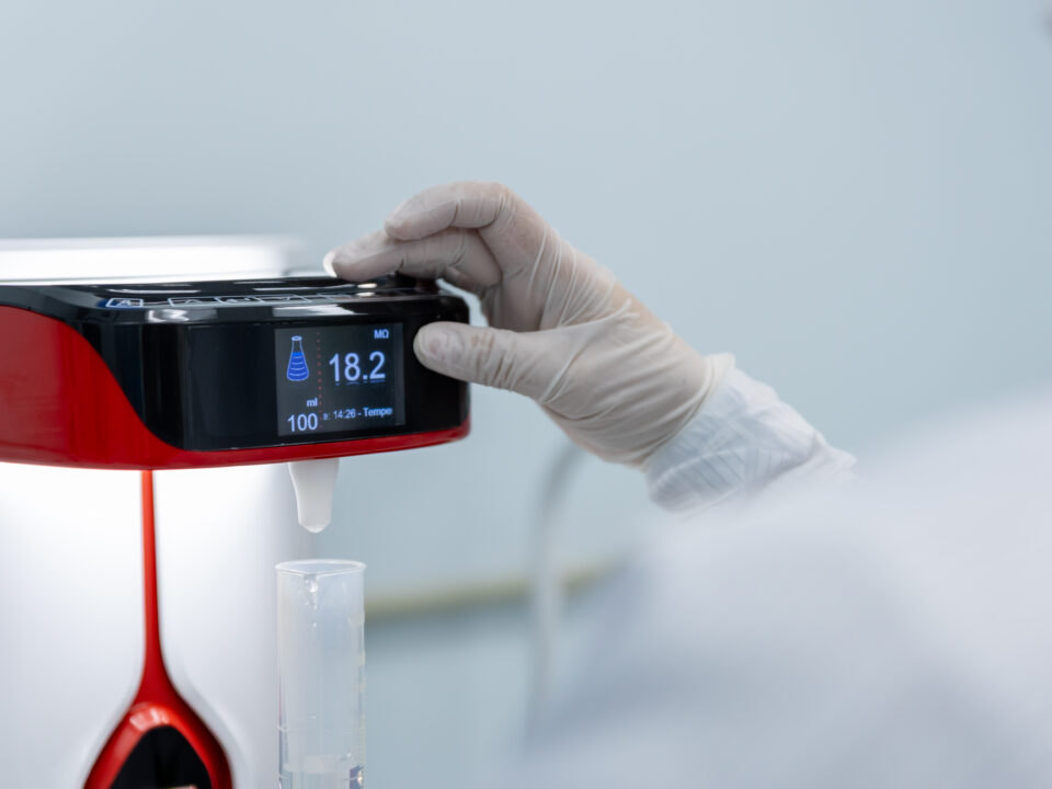
Anion/Cation Analysis · Ion Chromatography · GCMS · ICP-MS · RoHS/REACH Compliance · PCB Testing
ISO/IEC 17025 Accredited | Anion Test Specialist | Full Chemical Analytical Suite
The automotive industry’s shift toward electronics-intensive vehicle architectures, from advanced driver assistance systems (ADAS) to battery electric powertrains, has fundamentally changed the chemical testing requirements of automotive supply chains. Modern vehicles contain hundreds of electronic control units, kilometres of wiring, and sophisticated PCB assemblies whose reliability depends critically on chemical cleanliness, ionic contamination control, and compliance with global hazardous substance regulations.
At the same time, automotive chemical testing encompasses traditional analytical disciplines that remain essential: trace element analysis by ICP-MS, organic compound identification by GCMS, REACH and RoHS substance screening, and the growing discipline of ion chromatography for ionic contamination measurement, the ‘anion test’ that has become a critical quality control tool for automotive electronics manufacturers.
ALS Testing provides a comprehensive suite of chemical and electronics testing services, combining specialist ion chromatography capability with broad analytical chemistry capacity across ICP-MS, GCMS, FTIR, and regulatory compliance screening. With anion testing reaching search volumes of 210 per month in Malaysia – and no competitor currently offering well-developed content on this topic in the Malaysian market – ALS has a clear opportunity to establish content authority and capture this commercially significant keyword cluster.
Ion Chromatography – Anion & Cation Analysis
Ion chromatography (IC) is an analytical technique that separates and quantifies ionic species, both anions and cations, dissolved in an aqueous extract. In automotive and electronics testing, IC is applied to measure ionic contamination on component surfaces, in process fluids, and in assembly environments. The ‘anion test’ is shorthand for ion chromatography analysis of anionic species, has become one of the most widely applied quality control tests in automotive electronics manufacturing.
What Is Anion Testing?
Anion testing by ion chromatography quantifies the concentration of negatively charged ionic species, particularly chloride (Cl⁻), fluoride (F⁻), sulfate (SO₄²⁻), nitrate (NO₃⁻), phosphate (PO₄³⁻), and a range of organic acid anions including acetate, formate, and oxalate, in an aqueous extract of a component or material. These anions are of critical concern in automotive electronics because many of them are aggressive corrosion initiators and electrolytic conductors that can cause:
Electrochemical corrosion of metal conductors and contact surfaces
Dendritic growth (metallic whisker growth between PCB conductors under voltage bias)
Leakage current increase that triggers false signals in sensitive electronic circuits
Delamination of PCB laminates and conformal coatings in the presence of moisture
Accelerated corrosion of solder joints and connector contacts
In automotive applications, the primary source of ionic contamination is residual flux from PCB soldering processes, particularly when no-clean flux residues are not fully removed or when water-soluble flux residues are inadequately cleaned. Process water, fingerprints, environmental deposition, and chemical exposure during manufacturing are secondary sources.
Ion Chromatography Test Method – IPC-TM-650 2.3.28 / J-STD-001
The primary standard for ionic contamination testing of PCB assemblies is IPC-TM-650 Method 2.3.28, which defines the extraction method (a mixture of isopropyl alcohol and water applied to the PCB surface) and specifies the ion chromatography analysis for both anions and cations. The J-STD-001 standard (Requirements for Soldering Electrical and Electronic Assemblies) references cleanliness requirements that may require IC analysis for qualification.
ALS conducts ionic contamination testing by IC to IPC-TM-650 2.3.28, providing results in µg/cm² for each ionic species identified, against the limits specified by the client’s cleanliness specification or OEM requirement. Results identify both the type and quantity of each ionic species, enabling manufacturers to verify compliance and infer potential root causes (such as chloride excess suggesting flux residue or organic acids suggesting flux decomposition products).
Cation Analysis – Sodium, Potassium, Ammonium & Others
In addition to anion analysis, ALS provides cation analysis by IC for the principal positively charged ionic species of concern in electronics: sodium (Na⁺), potassium (K⁺), ammonium (NH₄⁺), and the amines associated with no-clean flux formulations (particularly methylamine and triethanolamine, which are characteristic of amine-based flux activators). Elevated ammonium or amine concentrations can indicate inadequate removal of flux activator residues, which in combination with humidity can cause under-board corrosion and leakage current failures.
RoHS & REACH Compliance Testing
The Restriction of Hazardous Substances (RoHS) Directive and the Registration, Evaluation, Authorisation and Restriction of Chemicals (REACH) Regulation are the two most significant global regulatory frameworks governing chemical content in electrical and electronic products. Compliance with both is mandatory for automotive electronics products supplied to the EU market, and is increasingly required by global OEMs as a contractual supply chain requirement regardless of the target market.
RoHS Compliance Screening – IEC 62321 Series
The RoHS Directive restricts the use of six hazardous substances in electrical and electronic equipment: lead (Pb), mercury (Hg), cadmium (Cd), hexavalent chromium (Cr(VI)), polybrominated biphenyls (PBB), and polybrominated diphenyl ethers (PBDE). RoHS 2 (Directive 2011/65/EU and its amendments) added four phthalates (DEHP, BBP, DBP, and DIBP), making ten restricted substances in total.
ALS provides RoHS compliance screening to the IEC 62321 series of test methods, which defines the analytical methods for determination of each restricted substance group. Screening begins with X-ray fluorescence (XRF) screening for elemental species (Pb, Hg, Cd, Cr) and proceeds to confirmatory quantitative analysis by ICP-MS or ICP-OES where XRF screening indicates potential exceedance. Hexavalent chromium is determined specifically by UV-Vis spectrophotometry, and phthalates are determined by GCMS.
REACH – SVHC Screening
The REACH regulation requires declaration of substances of very high concern (SVHC) in articles above a concentration threshold of 0.1% w/w, when the SVHC concentration exceeds 0.1% in the article as a whole. The SVHC candidate list, published by the European Chemicals Agency (ECHA) and updated regularly, now contains over 230 substances, including phthalates, heavy metals, aromatic amines, certain polymers, and flame retardants. ALS provides targeted SVHC screening for the substances most commonly encountered in automotive materials and electronic components, using appropriate analytical methods including XRF, ICP-MS, GCMS, and IC.
GCMS – Organic Chemical Analysis
Gas chromatography-mass spectrometry (GCMS) is the primary analytical tool for identification and quantification of organic compounds, including solvents, plasticisers, flame retardants, process chemicals, and contaminants in automotive materials and components. In automotive chemical testing, GCMS is applied across a range of programmes.
GCMS Applications in Automotive Testing
VOC and SVOC emissions analysis: GCMS is the detection method used in thermal desorption analysis to VDA 278 and ISO 12219, providing a detailed compound-by-compound profile of organic emissions from interior materials. Contaminant identification: when unknown organic contaminants are found on component surfaces, in lubricants, or in process fluids, GCMS compound identification provides the molecular-level identification needed for source investigation and corrective action. Phthalate analysis for RoHS compliance: GCMS is the confirmatory method for determination of phthalates (DEHP, BBP, DBP, DIBP) in materials screened initially by XRF. Solvent and process chemical residue analysis: GCMS identifies residual solvents and cleaning agents on component surfaces after cleaning processes, providing evidence of adequate cleaning or contamination by inappropriate process chemicals.
ICP-MS & ICP-OES – Trace Element Analysis
Inductively coupled plasma mass spectrometry (ICP-MS) and inductively coupled plasma optical emission spectrometry (ICP-OES) are the premier techniques for trace and ultra-trace elemental analysis in automotive materials, process fluids, and environmental samples. These techniques provide multi-element analysis at concentrations from percentage levels (ICP-OES) down to parts per trillion (ICP-MS) in dissolved samples, making them essential tools for restricted element screening, material composition verification, and contamination source tracing.
Trace Element Analysis Applications
RoHS element screening: ICP-MS and ICP-OES provide confirmatory quantitative analysis for lead, mercury, cadmium, and total chromium in materials where XRF screening has indicated potential RoHS exceedance. Automotive fluid analysis: engine oils, coolants, hydraulic fluids, and gear lubricants are analysed by ICP-OES for wear metals (iron, copper, aluminium, chromium), additive elements (zinc, phosphorus, molybdenum), and contaminant elements as part of condition monitoring and failure investigation programmes. Material composition verification: ICP analysis confirms the elemental composition of alloys, platings, and surface treatments against specified composition limits. Environmental sample analysis: ALS applies ICP-MS to environmental water and soil samples in support of automotive manufacturing facility environmental monitoring and regulatory compliance programmes.
PCB & Electronics Component Testing
Automotive electronics components, including PCBs, connectors, sensors, power modules, and wire harness assemblies, are subject to some of the most demanding chemical cleanliness and material compliance requirements in the electronics industry. The consequences of chemical contamination in automotive safety systems, powertrain controls, or battery management electronics are severe, ranging from intermittent operation through to complete functional failure in safety-critical systems.
PCB Ionic Contamination Testing
Ion chromatography analysis of PCB ionic contamination (IPC-TM-650 2.3.28) is described in detail in the Ion Chromatography section above. ALS provides this as a standard service for automotive PCB manufacturers and assemblers, supporting both production quality control and OEM qualification requirements.
Solderability Testing
Solderability testing evaluates the wettability of component leads, PCB pads, and solder surfaces, specifically the ability of liquid solder to spread uniformly across a surface. Poor solderability leads to cold solder joints, dewetting, and non-wet opens, which are a significant source of early-life failures in automotive electronics. ALS provides solderability testing by wetting balance (J-STD-002) and dip-and-look methods (IPC-TM-650 2.4.12) to support incoming component qualification and process control.
Conformal Coating Inspection & Analysis
Conformal coatings applied to automotive PCBs provide protection against moisture, contamination, and mechanical stress. ALS provides analysis of conformal coating composition by FTIR to verify coating type, cross-section analysis by optical and scanning electron microscopy to assess coating thickness and uniformity, and adhesion testing to evaluate bonding integrity of the coating to the PCB surface. These tests support both coating process validation and investigation of coating failures in field-returned assemblies.
Standards & Test Methods
Standard / Method
Technique
Application
IPC-TM-650 2.3.28
Ion Chromatography (IC)
PCB ionic contamination – anion and cation analysis
J-STD-001
Multiple
Soldering cleanliness requirements – references IC for qualification
IEC 62321-1 to -8
XRF, ICP-MS, ICP-OES, GCMS, UV-Vis
RoHS restricted substance screening and confirmatory analysis
REACH SVHC
XRF, ICP-MS, GCMS, IC
SVHC substance screening in automotive materials and articles
VDA 278
Thermal Desorption GCMS
VOC and FOG emissions from interior materials – German OEM
ISO 12219
Chamber / GCMS
Interior air VOC analysis – international standard
ISO/IEC 17025
Quality Management System
Accreditation framework for all ALS analytical methods
ICP-MS / ICP-OES
Elemental Analysis
Trace element quantification – fluids, materials, coatings
GCMS (Full Scan / SIM)
Organic Compound ID & Quantification
Contaminant ID, RoHS phthalates, VOC analysis
J-STD-002
Wetting Balance
Solderability testing – component leads and PCB pads
Why ALS for Chemical & Electronics Testing?
Specialist in Ion Chromatography – Anion Test Leader in Malaysia
ALS Testing offers one of the most comprehensive ion chromatography capabilities in the Malaysian testing market, covering the full range of ionic species relevant to automotive electronics quality control: fluoride, chloride, nitrite, phosphate, sulfate, acetate, formate, oxalate, and the organic acid anions characteristic of no-clean flux residue. Our IC capability covers both anion and cation analysis in a single analytical run, providing a complete ionic profile from a single sample extraction.
With anion test searches at 210 per month in Malaysia and no competitor currently providing a well-developed digital resource on this topic, ALS is positioned to be the definitive reference for automotive electronics manufacturers in the region seeking ion chromatography testing services.
Full Analytical Suite Under One Roof
Rather than working with multiple specialist laboratories for different analytical disciplines, ALS clients benefit from access to our full analytical suite: IC, ICP-MS, ICP-OES, GCMS, FTIR, SEM-EDX, and XRF under a single ISO/IEC 17025 accredited quality management system. This simplifies sample management, reduces logistics complexity, and ensures consistency of sample handling across all analytical techniques applied to the same investigation.
Automotive Context & Application Knowledge
Chemical analysis in automotive applications requires more than analytical technique proficiency; it requires understanding of where contamination comes from, why it matters in context, and how analytical results translate into manufacturing and quality decisions. ALS analysts have experience in automotive manufacturing environments and understand the quality questions that drive testing requests. This enables us to provide results and interpretations that are directly actionable, rather than raw analytical numbers that require translation.
Frequently Asked Questions – Chemical & Electronics Testing
Q: What is an anion test and why is it important for PCB manufacturing?
An anion test is ion chromatography (IC) analysis of ionic contamination on a PCB or electronic component surface, specifically targeting negatively charged ionic species including chloride, fluoride, sulfate, nitrate, phosphate, and organic acid anions. These anions are important in PCB manufacturing because they are the primary ionic contaminants that cause electrochemical corrosion, dendritic growth, and leakage current failures in PCB assemblies, particularly in humid environments. The anion test is conducted to IPC-TM-650 Method 2.3.28 and provides results in µg/cm², comparable to OEM or IPC cleanliness acceptance limits.
Q: What is the difference between RoHS and REACH, and does ALS test for both?
RoHS (Restriction of Hazardous Substances Directive) restricts the use of ten specific hazardous substances in electrical and electronic equipment placed on the EU market: six original substances (lead, mercury, cadmium, hexavalent chromium, PBB, PBDE) plus four phthalates added by RoHS 2. REACH is a broader chemical regulation requiring identification and communication of substances of very high concern (SVHC) in articles. The SVHC candidate list contains over 230 substances. ALS provides compliance screening for both RoHS and REACH, using appropriate analytical methods for each substance category. We can provide a combined RoHS and REACH SVHC screening programme from a single sample submission.
Q: Can ALS identify unknown contaminants on automotive components?
Yes. Unknown contaminant identification is one of our most commonly requested analytical services. Our approach typically begins with FTIR analysis to identify organic contaminants and provide a rapid initial classification. SEM-EDX is applied to characterise the morphology and elemental composition of inorganic contaminants or particles. GCMS provides definitive molecular identification of organic species when FTIR yields an ambiguous or incomplete result. ICP-MS can quantify trace elements in dissolved contaminants. By applying this suite of techniques in sequence, ALS can identify the chemical nature and likely source of most contaminants encountered in automotive manufacturing environments.
Q: How do I interpret ion chromatography results for my PCB cleanliness specification?
IC results for PCB ionic contamination are typically expressed as µg/cm² of each ionic species, calculated from the total extracted mass divided by the board surface area analysed. These results are compared against the cleanliness acceptance limit specified by your OEM, your customer’s specification, or a standard such as IPC-7711. Common acceptance limits range from 0.2 µg/cm² to 1.56 µg/cm² for total ionic contamination, depending on the application’s criticality. Our report will state the measured concentration of each ionic species and compare it against your specified limit to provide a clear technical conclusion regarding compliance. If you need guidance on interpreting results or selecting appropriate cleanliness limits for your application, our technical team is available to advise.
Q: Does ALS provide GCMS analysis for VOC testing as well as RoHS phthalate screening?
Yes. Our GCMS capability covers both applications and more. For VOC/FOG emissions analysis, GCMS is the detection method used in thermal desorption analysis to VDA 278, providing compound identification and quantification of organic emissions from automotive interior materials. For RoHS phthalate screening, GCMS is the confirmatory analytical method applied after XRF screening for samples that require quantitative phthalate determination. Additionally, GCMS is applied to unknown contaminant identification, solvent residue analysis, process chemical characterisation, and environmental sample analysis. Our GCMS systems operate in full-scan mode for compound identification and selected ion monitoring (SIM) mode for trace-level quantification.
Request a Chemical & Electronics Testing Quote
From anion/cation analysis of PCB assemblies to RoHS compliance screening, GCMS contaminant identification, and ICP-MS trace element analysis, ALS Testing provides the chemical and electronics testing services that automotive electronics manufacturers in Malaysia and Southeast Asia require. Our ISO/IEC 17025 accredited results are accepted by global OEMs, and our specialist ion chromatography capability makes us the leading choice for automotive ionic contamination testing in the region.
→ Request a Quote: https://www.alstesting.co.th/request-a-quote/
→ Back to Automotive Testing Hub: /automotive-testing/
ISO/IEC 17025 Accredited | Ion Chromatography Specialist | RoHS + REACH + Anion/Cation Testing
Read moreApril 24, 2026
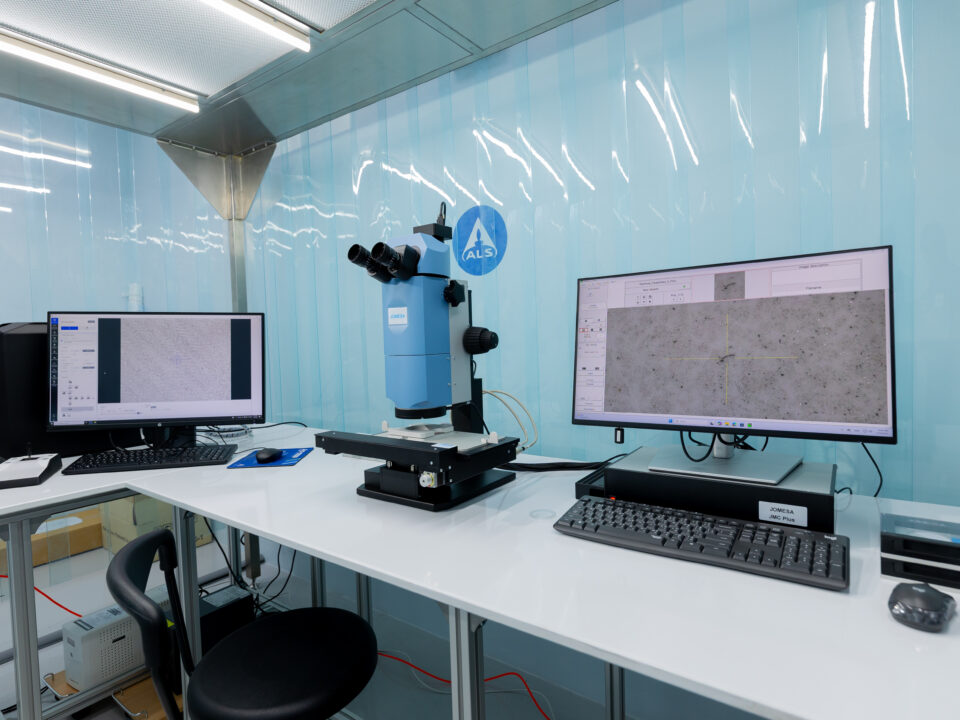
ISO/IEC 17025 Accredited | Cleanliness · Failure Analysis · Materials · Chemical Testing
ISO 17025 Accredited | ILAC MRA | 40+ Years Global Network
Every automotive component failure begins with something invisible: contamination, material degradation, or an undetected defect. In today’s automotive manufacturing landscape, where tolerance for error is measured in microns and regulatory pressure increases with every new model cycle, the stakes of unvalidated components have never been higher.
Manufacturers across Malaysia and Southeast Asia face mounting pressure from multiple directions: more complex EV platforms, tighter OEM specification requirements, increasingly stringent chemical and emissions standards, and supply chains that span continents. A single undetected particle in a hydraulic system, a material that off-gasses beyond permissible limits, or a PCB with ionic contamination that escapes to field conditions. All of these can trigger warranty claims, production shutdowns, and reputational damage that far exceeds the cost of proper testing.
ALS Testing is an independent, ISO/IEC 17025 accredited third-party laboratory providing comprehensive automotive testing services to OEMs, Tier-1 and Tier-2 suppliers, and automotive electronics manufacturers throughout Malaysia and Southeast Asia. With over 40 years of global experience across the ALS network and deep local expertise in the Malaysian and regional automotive market, ALS delivers the precision, objectivity, and internationally recognised results that modern automotive manufacturers require.
Explore our full range of automotive testing services below, from technical cleanliness and failure analysis to materials testing and chemical compliance screening.
What Is Automotive Testing?
Automotive testing is the systematic evaluation of materials, components, sub-assemblies, and complete vehicle systems to verify that they meet defined performance, safety, chemical, and regulatory specifications. It spans the entire manufacturing lifecycle, from raw material qualification through prototype validation, production quality control, and field failure investigation.
In scope, automotive testing covers a broad spectrum of disciplines: physical and mechanical testing of materials and structures; chemical analysis of coatings, fluids, and polymer compounds; cleanliness and contamination analysis of precision components and hydraulic systems; failure analysis of components returned from field or production; and environmental simulation testing to assess durability under real-world conditions including temperature cycling, humidity, corrosion, and vibration.
Testing can be classified in several ways. Destructive testing involves irreversible analysis (cross-sections, chemical extraction, or mechanical fracture testing) and yields the most detailed information about a component’s internal structure and material composition. Non-destructive testing (NDT) allows a component to be evaluated and returned to service, using techniques such as SEM imaging, X-ray inspection, or particle extraction. Testing can also be categorised by regulatory purpose: type approval testing confirms conformance to legal and OEM requirements for production intent components, while R&D testing supports early-stage development, material selection, and process optimisation.
Why Independent Automotive Testing Matters
Independent, third-party laboratory testing plays a central role in modern automotive manufacturing for three critical reasons.
First, regulatory and OEM acceptance: the vast majority of global OEMs require testing results from ISO/IEC 17025 accredited independent laboratories. In-house test reports, regardless of the sophistication of the equipment, are typically not accepted as compliance evidence for OEM approval processes, type approvals, or regulatory submissions. Accredited laboratory results carry a level of traceability and methodological rigour that in-house testing cannot formally provide.
Second, liability protection: when a component or material is tested by an independent laboratory, the test report provides documented, objective evidence of compliance at the time of manufacture. This evidence is critical in the event of warranty claims, product liability disputes, or regulatory investigations. An independent report reduces risk exposure for suppliers and protects against unjustified claims.
Third, objectivity and confidence: there is no conflict of interest in third-party testing. ALS operates independently of its clients and has no stake in any particular test outcome. Our results reflect reality, which is exactly what manufacturers, regulators, and end customers require.
ALS provides all of the above, with 40+ years of global expertise and a local team who understands the nuances of the Malaysian and Southeast Asian automotive supply chain.
Automotive Testing vs In-House Testing: Key Differences
The question of whether to conduct testing in-house or to outsource to a contract testing laboratory is one that many automotive suppliers face, particularly as they scale up production volumes or seek new OEM approvals. The decision involves multiple dimensions beyond simple cost comparison.
Dimension
In-House Testing
Third-Party Lab (ALS)
Accreditation
Typically not ISO/IEC 17025 accredited
ISO/IEC 17025:2017 accredited – ILAC MRA recognised
OEM Acceptance
Often not accepted for formal approval
Accepted by global OEMs and regulatory bodies
Equipment Scope
Limited to owned equipment
Full analytical suite: SEM, FTIR, EDX, ICP, GC-MS and more
Objectivity
Potential conflict of interest
Fully independent – no stake in outcome
Cost Structure
High fixed capex + maintenance
Variable cost – pay per test
Turnaround
Internal queues and priorities
Dedicated testing workflow
Regulatory Use
Internal QC only
Type approval, OEM submission, regulatory compliance
For most suppliers, the most effective approach is a combination: in-house QC for routine production monitoring, with outsourced third-party testing for OEM submissions, qualification testing, failure investigations, and regulatory compliance. ALS functions as a natural extension of your quality team in this hybrid model.
Our Automotive Testing Services
ALS Testing offers a comprehensive range of automotive testing services, with particular expertise in cleanliness testing and failure analysis, where many regional laboratories fall short. Our services are structured around five integrated disciplines that cover the full spectrum of automotive testing requirements, from component-level contamination analysis to environmental simulation and chemical compliance screening.
Cleanliness & Particle Testing (ISO 16232 / VDA 19)
ALS specialises in technical cleanliness testing to ISO 16232 and VDA 19, a capability that few laboratories in Malaysia and Southeast Asia can match. Our cleanliness testing services provide manufacturers of precision hydraulic components, fuel system parts, transmission assemblies, and braking system components with quantitative evidence that their products meet defined cleanliness classes.
Testing includes extraction of particles from component surfaces and channels, gravimetric analysis for mass-based cleanliness assessment, light obscuration particle counting (LPC) for size distribution and particle count, and microscopic analysis of extracted particles for material identification. This is one of ALS’s strongest competitive differentiators in the Malaysian market, a capability that competitors including SIRIM and Bureau Veritas do not offer at the same level of depth.
→ Explore our Cleanliness & Particle Testing services: ISO 16232 and VDA 19 cleanliness testing
Failure Analysis (SEM / FTIR / EDX)
Our failure analysis team uses scanning electron microscopy (SEM), FTIR spectroscopy, EDX elemental analysis, and cross-section preparation to identify the root causes of automotive component failures. Whether the failure originated in manufacturing, material selection, processing, or field conditions, our analysts have the tools and experience to trace it to its origin.
Failure analysis is applied across a wide range of scenarios: fracture surface analysis to determine whether a failure was fatigue-related, overload-driven, or corrosion-initiated; contaminant identification on component surfaces; delamination and adhesion failure analysis; and investigation of field returns from OEM warranty programmes. With scanning electron microscopy analysis reaching search volumes of 260 searches per month in Malaysia alone, this is one of the most commercially significant services in our portfolio.
→ Explore our Failure Analysis services: SEM, FTIR, and EDX failure analysis
Automotive Materials & Environmental Testing
From VOC emissions testing to ISO 12219 and VDA 278 through to salt spray corrosion testing to ISO 9227 and ASTM B117, and thermal shock simulation to IEC 60068. ALS validates that your materials and components survive the demands of real-world automotive use. Our materials and environmental testing services support material qualification, OEM specification compliance, and regulatory approval for automotive interior and exterior components.
Key capabilities include volatile organic compound (VOC) analysis for automotive interior air quality compliance, semi-volatile organic compound (SVOC) screening, fogging testing to ISO 6452, salt spray and humidity testing for corrosion resistance evaluation, and thermal cycling and vibration testing for durability qualification. The combined search volume for VOC and salt spray testing keywords in Malaysia exceeds 430 searches per month, reflecting strong commercial demand for these capabilities.
→ Explore our Materials & Environmental Testing services: VOC emissions testing and salt spray
Chemical & Electronics Testing
ALS provides anion and cation analysis by ion chromatography, GCMS trace chemical analysis, ICP-MS elemental analysis, RoHS and REACH compliance screening, and ionic contamination testing for PCB assemblies and automotive electronics components. Our chemical testing services support automotive electronics manufacturers in meeting the increasingly stringent chemical requirements of global OEM supply chains and international regulatory frameworks.
With anion testing search volumes of 210 per month in the Malaysian market, with no competitor currently offering a well-developed content resource on this topic. ALS has a clear opportunity to establish authority in this niche. Our ion chromatography capabilities cover the full range of ionic species relevant to automotive electronics: chloride, fluoride, sulfate, phosphate, and organic acid anions.
→ Explore our Chemical & Electronics Testing services: anion and cation analysis by ion chromatography
Industries We Serve
ALS Testing works with manufacturers, suppliers, and engineering teams across the full automotive value chain. Our accredited testing services are designed to meet the specific needs of each customer segment, from globally operating OEMs with complex multi-standard testing requirements to local Tier-2 suppliers seeking a reliable laboratory partner for production qualification.
OEM & Tier-1 Automotive Suppliers
For OEMs and Tier-1 suppliers, ALS provides component validation testing, type approval support, and testing to OEM-specific standards including BMW GS specifications, Ford WSS standards, Toyota TSM requirements, and general group standards from major European, American, and Japanese automotive manufacturers. Our ISO/IEC 17025 accreditation ensures that results are accepted without question at OEM technical centres worldwide.
Whether you require cleanliness class certification for a hydraulic valve body, failure analysis of a returned warranty component, or VOC emissions testing for interior trim materials, ALS has the capability and accreditation to support your supply chain quality requirements.
Electric Vehicle (EV) Manufacturers & Suppliers
As EV adoption accelerates across Southeast Asia, driven by government incentive programmes in Malaysia, Thailand, Indonesia, and Vietnam. ALS supports EV manufacturers and their supply chains with battery component cleanliness testing, thermal management material analysis, electric motor component failure investigation, and chemical analysis of battery electrolytes and electrode materials.
The unique testing challenges posed by EV platforms, from the cleanliness requirements of high-voltage battery assemblies to the ionic contamination risks in power electronics, map directly to ALS’s core competencies in cleanliness testing and chemical analysis. We are building our EV testing capability now to serve this rapidly growing market segment.
Automotive Electronics & PCB Manufacturers
From ionic contamination testing and anion/cation analysis by ion chromatography, through to RoHS/REACH compliance screening and solderability testing, ALS supports automotive electronics manufacturers with the precise chemical and reliability analysis that modern automotive electronics programmes demand. Automotive electronics are subject to some of the most stringent chemical cleanliness requirements in the electronics industry, driven by the safety-critical nature of automotive control systems.
Automotive Materials & Polymer Suppliers
ALS tests automotive-grade plastics, rubbers, foams, adhesives, coatings, and composite materials for VOC and SVOC emissions, restricted substance compliance, chemical resistance, and mechanical performance to VDA, ISO, and OEM specifications. Whether you supply instrument panel materials, headliner fabrics, underbonnet polymers, or structural adhesives, ALS can provide the testing evidence your OEM customers require.
Standards & Accreditations
Trust in laboratory testing results rests on a foundation of documented accreditation, methodological rigour, and equipment traceability. ALS Testing is accredited to ISO/IEC 17025:2017, the international standard for the competence of testing and calibration laboratories, by an accreditation body that is a signatory to the ILAC Mutual Recognition Arrangement (MRA).
ISO/IEC 17025:2017 Accreditation
ALS Testing is accredited to ISO/IEC 17025:2017, with results recognised under the ILAC MRA across more than 100 countries. This means that test reports issued by ALS are accepted by OEMs, regulatory bodies, and government agencies worldwide without the need for re-testing. The ILAC MRA is the global framework that enables laboratory results to cross borders with confidence, which is essential for automotive supply chains that operate across multiple markets.
Our accreditation covers a defined scope of tests, with accredited test methods listed in our schedule of accreditation available from our accreditation body. For any test conducted within our accredited scope, our reports carry the formal ILAC MRA mark, confirming that the result was produced under a quality management system that meets the highest international standards for laboratory competence.
Key Automotive Standards We Test To
ALS testing capabilities span the major international and OEM-specific standards that govern automotive material, component, and electronics testing. The following table provides a reference overview of the key standards applied across our automotive testing scope.
Standard
Full Name
Category
Applied In
ISO 16232
Road Vehicles – Cleanliness of Components
Cleanliness Testing
Hydraulic, fuel, braking systems
VDA 19
Testing of Technical Cleanliness
Cleanliness Testing
Precision components – German OEM standard
VDA 278
Volatile Organic Compounds from Non-metallic Materials
VOC / Emissions
Automotive interior air quality
ISO 12219
Interior Air of Road Vehicles
VOC / Emissions
Cabin VOC and SVOC measurement
VDA 275
Formaldehyde Emission – Photometric Analysis
Chemical Emissions
Interior materials – formaldehyde
ISO 9227
Corrosion Tests – Salt Spray Apparatus
Environmental / Corrosion
Metal components, coatings, fasteners
ASTM B117
Salt Spray (Fog) Apparatus
Environmental / Corrosion
General corrosion testing – US standard
IEC 60068
Environmental Testing for Electronic Products
Environmental Simulation
Automotive electronics components
IPC-TM-650
Test Methods Manual – PCB & Electronics
Electronics Testing
PCB ionic contamination, solderability
REACH
Registration, Evaluation, Authorisation of Chemicals
Chemical Compliance
Restricted substances – EU directive
RoHS Directive
Restriction of Hazardous Substances
Chemical Compliance
Electronics – hazardous substance limits
Why Choose ALS Testing?
In a market where testing laboratories are not in short supply, the quality of the laboratory you choose to partner with has direct consequences for your OEM relationships, your regulatory compliance posture, and your ability to respond to product quality issues quickly and with confidence. ALS Testing differentiates itself across four key dimensions that matter most to automotive manufacturers.
Specialist in Cleanliness & Failure Analysis
ALS Testing brings specialist-level expertise in automotive cleanliness testing to ISO 16232 and VDA 19, and failure analysis using SEM, FTIR, and EDX, capabilities that few laboratories in Malaysia can match at this depth. While major competitors in the Malaysian market offer general testing services, cleanliness testing and advanced failure analysis require specialised equipment, methodological experience, and analysts who understand automotive manufacturing processes. ALS has invested in building this expertise, and it represents our strongest point of competitive differentiation in the regional market.
ISO/IEC 17025 Accredited – Globally Recognised Results
Our accredited test reports are accepted by OEMs and regulatory authorities across more than 100 countries under the ILAC MRA, giving you confidence in every result and eliminating the risk of results being rejected by your customer’s technical approval team. When you submit an ALS test report in support of an OEM qualification, a type approval application, or a regulatory submission, you are submitting a document that carries internationally recognised weight.
Part of a 40+ Year Global Testing Network
As part of the ALS global network, one of the world’s leading testing, inspection, and certification organisations, we combine world-class laboratory capabilities with deep local knowledge of the Malaysian and Southeast Asian automotive market. The ALS global network provides access to specialised testing capabilities, technical expertise, and reference resources that simply are not available at standalone regional laboratories. For automotive manufacturers with testing requirements that extend beyond our local scope, the global ALS network provides seamless access to the same quality standards in other markets.
Fast Turnaround & Responsive Technical Support
We understand that testing delays cost money. Production holds, delayed OEM submissions, and extended field investigation timelines all have real financial consequences. Our team is structured to provide fast turnaround times and proactive communication from the moment of sample receipt through to the delivery of your final test report. We treat every sample as if a production decision depends on it, because it often does.
Frequently Asked Questions (FAQ)
Q: What automotive testing services does ALS offer?
ALS Testing provides five core categories of automotive testing services
(1) Technical Cleanliness & Particle Testing to ISO 16232 and VDA 19;
(2) Failure Analysis using SEM, FTIR, EDX, and cross-section analysis;
(3) Automotive Materials & Environmental Testing including VOC, salt spray, and thermal simulation;
(4) Chemical & Electronics Testing including ion chromatography, GCMS, and RoHS/REACH compliance; and
(5) the full Automotive Testing Hub encompassing all of the above with OEM-standard test methods. Contact our team or visit the relevant service page for a detailed capability list.
Q: Is your laboratory accredited for automotive testing?
Yes. ALS Testing is accredited to ISO/IEC 17025:2017. Our test reports carry the ILAC MRA mark and are recognised by OEMs and regulatory bodies in more than 100 countries worldwide. Accreditation to ISO/IEC 17025 is the international gold standard for laboratory competence, and it means that every test result we produce has been generated under a formally validated quality management system with documented traceability to national and international measurement standards.
Q: Do you serve clients in Malaysia and other countries in the region?
Yes. ALS Testing primarily serves clients in Malaysia, and we also support manufacturers and suppliers in Thailand, Singapore, Indonesia, Vietnam, and other markets across Southeast Asia. Our ISO/IEC 17025 accreditation, recognised under the ILAC MRA, means that our test reports are accepted across all major global markets. For samples shipped from outside Malaysia, please contact us to discuss logistics and sample submission requirements.
Q: Can you test to OEM-specific standards such as BMW, Toyota, or Ford specifications?
Yes. ALS has experience with a range of OEM-specific test standards in addition to international standards such as ISO, VDA, and IEC. Please contact us with your specific requirements, including the OEM specification number and revision, and our technical team will confirm our capability and advise on the appropriate test method. For standards outside our current scope, we will advise whether the test can be conducted under the ALS global network.
Q: How do I submit samples and obtain a quote?
The process is straightforward
(1) Contact our team via the enquiry form at /contact/ or by telephone, providing details of the component, the test required, and the standard or specification;
(2) Our technical team will provide a quotation and sample submission instructions;
(3) Ship or deliver your samples to our laboratory;
(4) Testing is conducted and your report is issued electronically. For urgent requirements, please indicate this when making contact and we will advise on expedited options.
Q: What is the typical turnaround time for automotive testing?
Turnaround times vary depending on the test type, sample preparation requirements, and current laboratory workload. Simple chemical analyses may be completed within two to five business days, while complex failure analysis or multi-test programmes may require one to three weeks. Please contact our team when submitting your enquiry and we will provide a specific timeline estimate for your requirements. We also offer expedited service for time-critical investigations; please ask about this option if your situation requires faster results.
Request an Automotive Testing Quote
Ready to discuss your automotive testing requirements? Whether you need cleanliness certification for a precision component, a root cause failure analysis, VOC emissions testing for interior materials, or a comprehensive multi-test qualification programme, ALS Testing’s specialists are here to help, from initial sample submission guidance through to delivery of your final test report.
Our team makes the process simple. Tell us what you need, and we will provide a clear quotation, sample submission instructions, and a realistic timeline. For complex programmes, we can arrange a technical discussion to ensure that the test plan is fully aligned with your OEM or regulatory requirements.
→ Request a Quote: https://www.alstesting.co.th/contact-us/
→ Download Automotive Testing Capability Brochure
ISO/IEC 17025:2017 Accredited | Results trusted by OEMs worldwide | ILAC MRA Recognised
Read moreApril 24, 2026
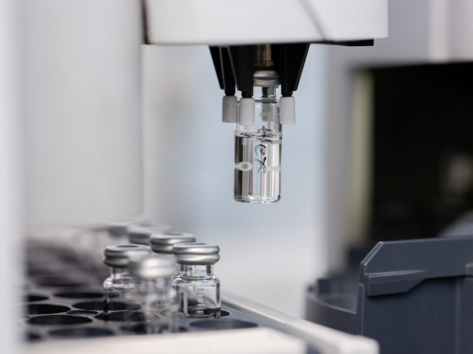
VOC Emissions · Salt Spray Corrosion · Thermal Testing · Interior Air Quality · VDA 278 · ISO 9227
ISO/IEC 17025 Accredited | Full Environmental Simulation Suite | OEM Standard Testing
The materials that make up a modern automobile are subjected to conditions that most materials would never encounter: temperature extremes from −40°C to +120°C and beyond; salt-laden road spray that attacks every exposed metal surface; UV radiation that degrades polymers and fades pigments; humid tropical heat that accelerates corrosion and swells seals; and the constant off-gassing requirements of interior materials that affect the air quality cabin occupants breathe every day.
Automotive materials testing, which encompasses VOC emissions analysis, corrosion testing, environmental simulation, thermal characterisation, and chemical content analysis, validates that materials and components survive these conditions and meet the specifications that OEMs and regulations define. With combined search volumes exceeding 430 searches per month in Malaysia for VOC and salt spray testing alone, this is one of the most commercially active testing categories in the regional automotive market.
ALS Testing is accredited to ISO/IEC 17025:2017 and offers a comprehensive range of automotive materials and environmental testing services, covering the key standards that govern material qualification for Malaysian and global automotive supply chains. Critically, ALS currently has no content covering VOC testing – the highest-volume keyword in our portfolio – making this Pillar Page a priority content investment.
VOC Emissions Testing for Automotive Interior Materials
Volatile organic compound (VOC) emissions from automotive interior materials are a significant concern for both regulatory compliance and consumer experience. Interior materials including instrument panels, headliners, seat foams, carpets, door trim panels, adhesives, and sealants all contribute to the volatile chemical environment inside the vehicle cabin. Elevated VOC concentrations in new vehicles have been associated with health concerns, including irritation, headache, and in extreme cases, sensitisation, and are subject to increasingly stringent OEM specifications and, in some markets, regulatory limits.
Automotive VOC testing is governed by several key standards that specify the test method, temperature conditions, sampling duration, and analytical approach. ALS provides testing to the primary automotive VOC standards required by global OEMs.
VDA 278 – Thermal Desorption Analysis of Automotive Interior Materials
VDA 278 is the German automotive industry standard for analysis of organic emissions from automotive interior components using thermal desorption GC-MS. The standard defines two heating stages: 90°C for VOC determination (volatile organic compounds) and 120°C for FOG determination (semi-volatile high-boiling condensable compounds, applied to a small sample of the material under controlled conditions. The emitted compounds are collected on a Tenax sorbent tube, thermally desorbed, and analysed by gas chromatography-mass spectrometry (GC-MS) to provide a quantitative profile of organic emissions.
VDA 278 is required by German OEMs (BMW, Volkswagen Group, Mercedes-Benz, Audi) and their Tier-1 suppliers, and is widely adopted across the global automotive supply chain. It provides quantitative data for comparison against specified emission limits for individual compounds and compound groups, typically expressed in µg/g of material.
ISO 12219 – Interior Air of Road Vehicles
ISO 12219 is the international standard series covering the measurement of VOC concentrations in vehicle interiors. The standard defines test methods for measuring VOC concentrations in the cabin air of complete vehicles (ISO 12219-1, bag method) and for emissions from individual interior components (ISO 12219-2 to ISO 12219-7, covering various chamber and micro-chamber methods). ALS provides component-level VOC testing to the ISO 12219 chamber methods, enabling material qualification against OEM VOC specifications defined under this standard.
VDA 275 – Formaldehyde Emission Testing
Formaldehyde is a specific VOC of regulatory and health concern, subject to dedicated test methods and specific emission limits in many OEM specifications. VDA 275 specifies a bottle method for determination of formaldehyde emissions from automotive interior non-metallic materials, using photometric analysis of the extracted formaldehyde. ALS provides formaldehyde testing to VDA 275 as part of our VOC testing capability, enabling clients to meet the specific formaldehyde limits defined by German and other OEMs.
ISO 6452 – Fogging Testing
Fogging testing determines the propensity of automotive interior materials to produce condensable vapours that deposit on the vehicle windscreen as a visible fog film. This is both an aesthetic issue (the fog film impairs driver visibility) and an indicator of high-boiling organic emissions from interior materials. ISO 6452 defines both photometric (reflectance-based) and gravimetric (mass deposition) methods for fogging assessment. ALS provides fogging testing to ISO 6452 as part of our interior emissions testing portfolio.
Corrosion & Salt Spray Testing
Corrosion is one of the most persistent and economically significant degradation mechanisms in automotive components and structures. Road salt, humid climates, and the electrochemical environment created by dissimilar metals in contact create conditions that attack metal surfaces, coatings, and plated surfaces continuously throughout a vehicle’s service life. Corrosion testing replicates these conditions in accelerated form, enabling assessment of coating quality, material selection, and corrosion protection effectiveness in a fraction of the real-world timescale.
ISO 9227 – Neutral Salt Spray Testing (NSS)
ISO 9227 is the primary international standard for salt spray (salt fog) corrosion testing, covering three test atmospheres: neutral salt spray (NSS), acetic acid salt spray (AASS), and copper-accelerated acetic acid salt spray (CASS). In the NSS test, the most widely applied, specimens are exposed to a continuously atomised 5% sodium chloride solution at 35°C for defined durations, typically ranging from 96 hours to 1,000 hours or more depending on the OEM specification. The standard defines the test apparatus requirements, solution chemistry, temperature tolerances, and evaluation criteria for assessing corrosion protection performance.
ALS salt spray testing to ISO 9227 is applied to painted and coated metal components, fasteners and fixings, electroplated surfaces, and automotive exterior and underbody components. Results are documented through visual examination of corrosion creep from scribe lines, blister formation, and spot corrosion. The resulting data is then classified according to ISO 10289, allowing manufacturers to verify compliance with their specific OEM requirements.
ASTM B117 – Standard Practice for Operating Salt Spray Apparatus
ASTM B117 is the American equivalent of ISO 9227 for neutral salt spray testing, widely required by American OEMs and their supply chains. The test conditions under ASTM B117 are equivalent to ISO 9227 NSS, with 5% sodium chloride solution at 35°C, but the evaluation criteria and acceptance requirements may differ between specifications. ALS can conduct salt spray testing to ASTM B117 for clients whose OEM specifications reference this standard.
Cyclic Corrosion Testing
While continuous salt spray testing (ISO 9227, ASTM B117) provides a standardised accelerated corrosion environment, cyclic corrosion testing, which alternates between salt spray exposure, humidity, ambient drying, and optional UV exposure phases, which many OEMs consider more representative of real-world corrosion progression. ALS offers cyclic corrosion testing to selected OEM and industry standards, providing a more nuanced assessment of corrosion protection performance for clients whose OEM specifications require this approach.
Thermal & Environmental Simulation Testing
Automotive components experience extreme thermal and environmental conditions during manufacture, assembly, shipping, and service. Environmental simulation testing replicates these conditions in controlled laboratory settings, enabling assessment of component integrity, material stability, and functional performance across the full environmental envelope.
Thermal Shock Testing (IEC 60068-2-14)
Thermal shock testing exposes components to rapid transitions between high and low temperature extremes, replicating the shock experienced by components during engine start-stop cycles, cold weather startup, or transition between heated and cooled environments. IEC 60068-2-14 specifies the thermal shock test method, defining the temperature extremes, transition time, dwell time at each extreme, and number of cycles. Thermal shock testing is applied to automotive electronics, sensors, connectors, and any component where thermal cycling could cause fatigue cracking, delamination, or seal failure.
Thermal Cycling & Temperature Endurance Testing (IEC 60068-2-1 / 2-2)
Thermal cycling testing exposes components to repeated temperature cycles between defined minimum and maximum temperatures, with controlled ramp rates and dwell times. Unlike thermal shock, cycling involves slower temperature transitions that stress materials through differential thermal expansion rather than rapid temperature shock. IEC 60068-2-1 covers cold testing and IEC 60068-2-2 covers dry heat testing. These methods are applied to automotive materials, electronics, and polymer components to assess stability and endurance across the operational temperature range.
Humidity & Damp Heat Testing (IEC 60068-2-78)
Humidity testing exposes components to elevated temperature and relative humidity conditions, assessing resistance to moisture ingress, hydrolytic degradation, corrosion, and swelling. IEC 60068-2-78 specifies the damp heat steady-state test at 40°C and 93% RH, widely applied to automotive electronics and connector systems. ALS humidity testing supports qualification of automotive electronics for tropical and humid climate markets including Southeast Asia, where humidity resistance is a particularly critical performance requirement.
Key Standards Reference – Materials & Environmental Testing
Standard
Test Type
Key Parameters
Typical Application
VDA 278
VOC/FOG Thermal Desorption
90°C VOC / 120°C FOG, GC-MS analysis
Interior trim, plastics, adhesives – German OEM
ISO 12219
Interior Air VOC
Chamber method, µg/m³ results
Interior material VOC qualification
VDA 275
Formaldehyde Emission
Bottle method, photometric
Interior materials – formaldehyde limits
ISO 6452
Fogging
Photometric / gravimetric, 100°C
Interior trim – windscreen fog assessment
ISO 9227 NSS
Salt Spray – Neutral
5% NaCl, 35°C, 96h to 1000h+
Metal components, coatings, fasteners
ISO 9227 AASS
Salt Spray – Acetic Acid
Acetic acid adjusted, 35°C
Aluminium alloys, decorative plating
ISO 9227 CASS
Salt Spray – Copper Accelerated
Copper chloride added, 50°C
Decorative chrome plating assessment
ASTM B117
Salt Spray – US Standard
5% NaCl, 35°C – ASTM method
American OEM supply chain
IEC 60068-2-14
Thermal Shock
Rapid transfer, −40°C to +150°C
Electronics, sensors, connectors
IEC 60068-2-1 / 2-2
Thermal Cycling
Defined ramp and dwell cycles
Automotive materials, electronics
IEC 60068-2-78
Damp Heat
40°C / 93% RH steady state
Automotive electronics – tropical climates
Industries & Applications
Automotive Interior Trim & Materials Suppliers
Suppliers of instrument panels, door trim, headliners, seat foams, floor carpets, and steering wheel covers require VOC emissions testing to VDA 278, ISO 12219, and VDA 275, as well as fogging testing to ISO 6452, to meet OEM interior air quality specifications. ALS provides the complete suite of interior emissions testing required for material qualification at German, Japanese, and American OEMs.
Metal Component & Fastener Manufacturers
Manufacturers of body-in-white components, underbody brackets, suspension parts, engine bay fasteners, and exterior fittings require salt spray testing to ISO 9227 and ASTM B117 to validate corrosion protection performance of coatings, platings, and surface treatments. ALS salt spray testing provides comprehensive performance data that suppliers use to verify compliance against OEM-specified corrosion resistance requirements.
Automotive Electronics & Sensor Manufacturers
ECUs, sensors, connectors, and power electronics components require thermal shock, thermal cycling, and humidity testing to IEC 60068 to demonstrate environmental robustness across the full automotive operating range. ALS environmental simulation testing supports qualification of automotive electronics for both temperate and tropical market applications.
Frequently Asked Questions – Materials & Environmental Testing
Q: What is VDA 278 and which OEMs require it?
VDA 278 is the German automotive industry standard for measuring organic emissions from non-metallic interior materials using thermal desorption gas chromatography-mass spectrometry. It is required by German OEMs including BMW, Volkswagen Group (Volkswagen, Audi, SEAT, SKODA, Porsche), Mercedes-Benz, and their direct suppliers. The standard provides both VOC and FOG (semi-volatile) results, expressed in µg/g of material, enabling material qualification through comparison against OEM-specified emission limits for individual compounds and compound groups.
Q: What is the difference between salt spray testing to ISO 9227 and ASTM B117?
ISO 9227 and ASTM B117 specify equivalent test conditions for neutral salt spray testing, both using 5% sodium chloride solution at 35°C, but they originate from different standards organisations (ISO vs ASTM) and may have different specification requirements in terms of evaluation methods and acceptance criteria. ISO 9227 is the standard required by most European and Asian OEM specifications, while ASTM B117 is required by American OEM specifications. ALS can test to either standard based on your OEM specification requirement.
Q: How long does a salt spray test take?
The duration of a salt spray test is defined by the OEM specification or the standard being tested to, and can range from 96 hours (4 days) for some coating qualification tests to 240, 500, or 1,000 hours for more demanding corrosion resistance requirements. Long-duration tests require advance planning and scheduling. Please contact our team early in your project timeline to allow for test scheduling, and to confirm whether interim inspection requirements are specified.
Q: Can ALS test for both VOC emissions and formaldehyde from the same material sample?
Yes. It is common for OEM specifications to require both general VOC/FOG analysis (by VDA 278) and specific formaldehyde determination (by VDA 275) from the same material. ALS can conduct both tests from a single sample submission, minimising the material required and simplifying the sample preparation and submission process. Please specify both test requirements when making your enquiry.
Request a Materials & Environmental Testing Quote
From VOC emissions qualification for interior trim materials to salt spray certification for exterior components and thermal shock testing for automotive electronics, ALS Testing provides the accredited materials and environmental testing services that automotive suppliers in Malaysia and Southeast Asia require. Contact our specialists to discuss your testing requirements and receive a quotation.
→ Request a Quote: https://www.alstesting.co.th/request-a-quote/
→ Back to Automotive Testing Hub: /automotive-testing/
ISO/IEC 17025 Accredited | VOC + Salt Spray + Thermal Specialist | German & International OEM Standards
Read moreApril 24, 2026
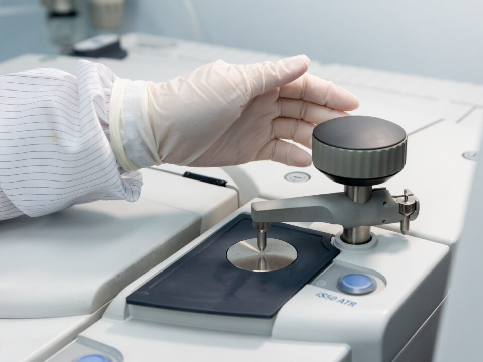
Root Cause Investigation · Fracture Analysis · Corrosion Analysis · Material Identification · Cross-Section
ISO/IEC 17025 Accredited | SEM + FTIR + EDX + Cross-Section | Automotive Specialist
When a component fails in production, in qualification testing, or in the field, the questions that matter most are not simply ‘what failed’ but ‘why did it fail’ and ‘how do we ensure it does not fail again.’ Failure analysis is the disciplined forensic process that answers these questions, tracing a visible failure mode back to its physical, chemical, or process root cause.
In the automotive industry, failure analysis is a critical tool across the entire product lifecycle. During development, it identifies design or material weaknesses before they reach production. During qualification, it explains unexpected test failures and guides corrective action. During production, it investigates non-conformances and prevents recurrence. After field returns, it determines warranty liability, informs recall decisions, and drives product improvement.
ALS Testing provides specialist automotive failure analysis services using scanning electron microscopy (SEM), FTIR spectroscopy, energy-dispersive X-ray spectroscopy (EDX), optical microscopy, and metallurgical cross-section preparation. With scanning electron microscopy analysis reaching 260 searches per month in the Malaysian market – the highest search volume in our entire keyword set – this is both the most technically demanding and the most commercially significant capability in our laboratory portfolio.
What Is Failure Analysis?
Failure analysis is the systematic investigation of a component or material to determine the cause of an unexpected failure, non-conformance, or performance deficiency. It applies a structured sequence of analytical techniques, starting with non-destructive visual and optical examination, progressing to surface and interface analysis, and culminating in destructive cross-section and microstructural examination where required, to identify the physical, chemical, or mechanical mechanism responsible for the failure.
In automotive applications, failure analysis encompasses a wide range of failure modes and component types. Fracture analysis investigates cracked or broken metal, polymer, or composite components, determining whether the fracture originated from fatigue, overload, corrosion, embrittlement, or manufacturing defects. Corrosion analysis characterises the type and extent of corrosion damage and identifies contributing factors including material composition, coating quality, and environmental exposure. Delamination and adhesion failure analysis investigates separation at material interfaces including bonded joints, coatings, plated surfaces, and polymer-to-metal bonds. Contamination analysis identifies foreign particles or films on component surfaces or in lubrication systems that have caused or contributed to functional failure.
Failure Analysis in the Automotive Supply Chain
The automotive supply chain applies failure analysis at multiple points where the stakes of unresolved failures are highest. Tier-1 suppliers conduct failure analysis on components returned from OEM qualification testing, where a single test failure can delay programme launch. Warranty teams investigate field returns to distinguish design defects from manufacturing escapes, and to determine whether failures within the warranty period are attributable to the supplier, the assembly process, or the OEM’s application conditions. Purchasing and quality teams use failure analysis to assess whether returned components represent genuine supplier non-conformances or misuse and handling damage by the customer. In each case, the failure analysis report provides objective, evidence-based conclusions that carry weight in technical and commercial disputes.
Why Choose an Accredited Independent Laboratory for Failure Analysis?
Failure analysis conducted by an ISO/IEC 17025 accredited independent laboratory carries a level of credibility that in-house analysis cannot replicate. When failure analysis results are used in OEM disputes, insurance claims, product liability proceedings, or regulatory investigations, the independence and accreditation of the laboratory that produced the analysis is routinely scrutinised. ALS provides analysis that is conducted under a formal quality management system, with documented traceability of methods and equipment calibration, and with the objectivity of an organisation that has no stake in any particular outcome.
Our Failure Analysis Techniques
ALS failure analysis employs a suite of complementary analytical techniques, selected based on the nature of the failure, the material types involved, and the level of detail required to reach a defensible root cause conclusion. Our analysts are experienced in applying these techniques in combination; a fracture surface analysis, for example, may combine optical microscopy for initial characterisation, SEM for high-magnification morphological analysis, and EDX for elemental mapping of fracture features.
Scanning Electron Microscopy (SEM) Analysis
Scanning electron microscopy is the central analytical tool for failure analysis at the micro and nano scale. SEM images component surfaces, fracture faces, and cross-section features at magnifications from 20x to 100,000x, with a depth of field and resolution that far exceeds optical microscopy. SEM analysis reveals fracture morphology, the characteristic features that distinguish fatigue striations from intergranular fracture from ductile overload; identifies surface defects, pits, cracks, and corrosion morphology at the micrometre scale; characterises particle morphology in contamination investigations; and provides the imaging foundation for EDX elemental analysis.
All SEM analysis at ALS is conducted in a controlled environment to minimise contamination, with samples prepared using appropriate techniques for the material type, including gold or carbon sputter coating for non-conducting samples. SEM images are documented with scale bars, magnification, and operating conditions for full traceability in the final report.
Energy-Dispersive X-Ray Spectroscopy (EDX) Elemental Analysis
EDX is used in combination with SEM to provide elemental composition data from specific points, areas, or features on a sample surface. By detecting the characteristic X-rays emitted from a sample under electron beam excitation, EDX identifies which elements are present and at what relative concentrations. In failure analysis, EDX is applied to identify corrosion products (for example, distinguishing chloride-induced pitting from sulfate-driven corrosion), to characterise contaminating particles (distinguishing iron from aluminium from silicon-based particles), to verify coating composition, and to detect elemental segregation or depletion at fracture interfaces.
EDX mapping provides a spatial elemental distribution image across an area of interest, enabling visualisation of where specific elements are concentrated; for example, showing the distribution of zinc in a galvanic corrosion zone, or the localisation of chlorine at a corrosion initiation site.
FTIR Spectroscopy (Fourier Transform Infrared)
FTIR spectroscopy is the primary technique for identification of organic materials, polymers, coatings, and surface films in failure analysis. By measuring the infrared absorption spectrum of a material, FTIR produces a molecular fingerprint that can be matched against reference libraries to identify polymer types, adhesive formulations, lubricant residues, and contaminating films. FTIR is routinely applied in automotive failure analysis to identify: the composition of failed gaskets and seals; contaminating films on metal surfaces that inhibit adhesion or coating bonding; degraded or thermally oxidised polymer components; lubricant composition and degradation state; and foreign material contaminants found at failure sites.
ALS operates both standard FTIR for bulk material analysis and ATR (attenuated total reflectance) FTIR for surface film analysis, enabling characterisation of films as thin as a few micrometres without the need for destructive extraction.
Optical Microscopy & Stereo Microscopy
Optical microscopy at magnifications from 10x to 1000x provides the initial visual characterisation stage of failure analysis, identifying fracture locations, corrosion zones, delamination interfaces, and gross defects before higher-resolution SEM analysis is applied. Stereo microscopy at lower magnifications (7x to 50x) provides three-dimensional surface imaging of fracture faces and component surfaces with excellent depth of field, enabling documentation of large-area failure features in context. All optical microscopy images are captured digitally and documented with magnification and scale information.
Metallurgical Cross-Section Preparation & Analysis
Cross-section preparation involves embedding a component in resin, cutting through the area of interest, grinding and polishing to a metallographic finish, and optionally etching to reveal microstructural features, providing access to the internal structure of a component at the site of failure. Cross-section analysis reveals coating thickness and uniformity, interface integrity between layers, crack propagation paths and morphology, grain structure and phase distribution in metals, porosity and inclusion content in castings, and the presence of decarburisation, carburisation, or other surface treatments. Combined with SEM and EDX analysis of the prepared cross-section, this technique provides the most comprehensive internal characterisation of a failed component.
Failure Modes We Investigate
ALS failure analysis services address the full spectrum of failure modes encountered in automotive component manufacturing and service.
Fracture & Fatigue Failure Analysis
Fracture surfaces carry a detailed record of the failure mechanism, encoded in the morphological features of the fractured faces. Fatigue fractures display characteristic features including fatigue crack initiation sites, beach marks (progression marks showing crack growth over cycles), and fatigue striations at high magnification. Overload fractures show ductile features (dimples, shear lips) or brittle features (cleavage facets, intergranular separation) depending on material and loading conditions. ALS fractography, the systematic analysis of fracture surfaces, determines the failure mode, identifies the initiation site, and assesses whether the failure was consistent with design intent, an unexpected overload, or a material or manufacturing defect.
Corrosion & Surface Degradation Analysis
Corrosion failures in automotive components can take many forms: general uniform corrosion, pitting corrosion localised at surface defects or inclusions, galvanic corrosion at bimetallic interfaces, crevice corrosion in confined geometries, stress corrosion cracking in susceptible alloys under mechanical loading, and fretting corrosion at vibrating contacts. ALS corrosion analysis characterises the corrosion morphology by optical and SEM microscopy, identifies corrosion products by EDX elemental analysis and FTIR spectroscopy, and assesses the contribution of material composition, surface treatment quality, and environmental exposure to the observed damage.
Delamination & Adhesion Failure Analysis
Failures at material interfaces, including between coatings and substrates, bonded surfaces, plated layers and base materials, and moulded polymer overmoulds and metal inserts, are among the most common and commercially significant failures in automotive components. ALS investigates delamination failures by cross-section analysis to characterise the interface morphology, SEM and EDX analysis of both separated surfaces to determine the locus of failure (cohesive failure within a layer, or adhesive failure at the interface), and FTIR analysis to identify contaminating films or inadequate surface preparation that may have compromised adhesion.
Contamination & Foreign Material Analysis
Contaminating particles, films, or deposits on component surfaces can cause a range of functional failures from corrosion initiation to electrical resistance increase to mechanical interference. ALS contamination analysis applies the full suite of SEM, EDX, FTIR, and optical microscopy techniques to characterise contaminants and identify their source. This is frequently applied to investigation of corrosion-related warranty failures where a chloride, sulfate, or organic acid contaminant has initiated pitting or crevice corrosion, and to investigation of electrical contact failures where surface films have increased contact resistance.
Our Failure Analysis Process
ALS failure analysis follows a structured investigation process that ensures comprehensive characterisation and defensible conclusions in every case.
Stage
Activity
Output
1. Receipt & Review
Sample receipt, condition documentation, review of client background information
Sample condition record, investigation brief
2. Non-Destructive Examination
Visual, stereo, and optical microscopy – photographic documentation
Overview images, failure site characterisation
3. Surface Analysis
SEM imaging, EDX elemental analysis, FTIR surface film analysis
High-resolution images, elemental data, material identification
4. Destructive Examination
Cross-section preparation, metallographic analysis, SEM/EDX of cross-section
Internal structure characterisation, interface analysis
5. Data Synthesis
Integration of all analytical data, root cause determination, corrective action guidance
Draft failure analysis report
6. Reporting
Final report with images, data, conclusions, and recommendations
Formal failure analysis report – ISO/IEC 17025 accredited
Frequently Asked Questions – Failure Analysis
Q: What information should I provide when submitting a component for failure analysis?
The quality of a failure analysis investigation is directly related to the quality of the background information provided. When submitting a sample, please provide a description of the component and its function, the failure mode observed such as fracture, corrosion, or delamination, and details on when and how the failure was discovered in production, qualification, or the field. It is also helpful to include the operational history of the component if known, any relevant manufacturing information like material specification, heat treatment, surface treatment, and assembly history, and the specific outcome you require from the investigation. This could include root cause identification, technical evidence for specification compliance, or corrective action recommendations. The more context you provide, the more focused and relevant our investigation can be.
Q: How long does a failure analysis investigation take?
Turnaround time depends on the complexity of the investigation, the number of techniques required, and the current workload of our analytical team. A straightforward fracture analysis using SEM and EDX can typically be completed within five to ten business days. More complex investigations involving cross-section preparation, FTIR analysis, and comparative testing of multiple samples may require two to four weeks. For urgent investigations, particularly production-critical failures, please contact our team directly to discuss expedited options.
Q: Can failure analysis results be used in legal or commercial disputes?
Yes. Failure analysis reports produced by ISO/IEC 17025 accredited laboratories are routinely used as technical evidence in commercial disputes, insurance claims, product liability proceedings, and regulatory investigations. The accreditation of ALS Testing means that our reports are produced under a formally audited quality management system, with documented traceability of methods, equipment, and analyst qualifications. If your investigation has a legal or commercial dimension, please advise our team at the outset so that we can ensure the investigation is conducted and documented to the appropriate standard.
Q: What is SEM analysis and why is it important for failure analysis?
Scanning electron microscopy (SEM) is a technique that uses a focused electron beam to image surfaces at very high magnification and resolution. Unlike optical microscopy, SEM can achieve magnifications of 100,000x or higher with a depth of field that makes it ideal for imaging rough fracture surfaces, corroded surfaces, and three-dimensional microstructural features. SEM is important for failure analysis because it reveals the micro-scale morphological evidence that distinguishes one failure mechanism from another: fatigue striations, cleavage facets, corrosion pits, and particle morphology are all characteristic features that guide the analyst’s conclusion about root cause.
Q: Can ALS analyse plastic, rubber, and composite material failures as well as metals?
Yes. ALS failure analysis services cover metals, polymers, rubbers, composites, adhesives, coatings, and electronics materials. FTIR spectroscopy is our primary tool for polymer and organic material characterisation, enabling identification of polymer type, degradation state, and contaminating species. SEM and EDX analysis are applied to polymer fracture surfaces, interface failures, and contaminant identification in non-metallic components. Our analysts have experience with the full range of materials used in automotive manufacturing.
Request a Failure Analysis Investigation
When a component failure requires expert investigation, ALS Testing provides the analytical depth, accredited methodology, and clear reporting that automotive manufacturers require. Contact our team today to discuss your failure analysis requirements and receive guidance on sample submission.
→ Request a Quote: https://www.alstesting.co.th/request-a-quote/
→ Back to Automotive Testing Hub: /automotive-testing/
ISO/IEC 17025 Accredited | SEM + FTIR + EDX + Cross-Section | Fast Turnaround Available
Read moreApril 24, 2026
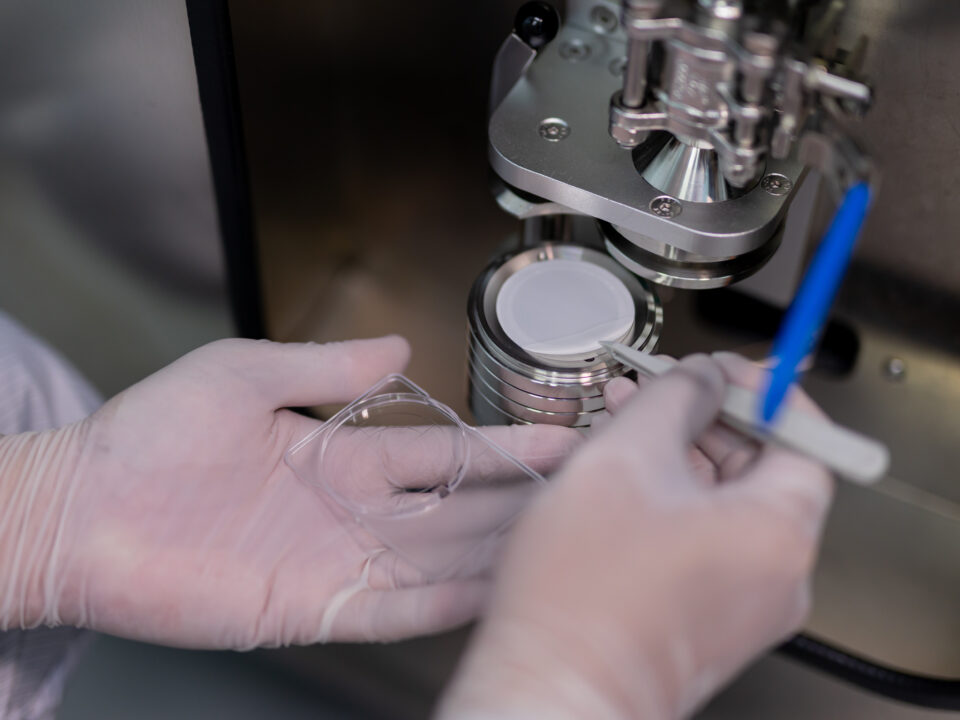
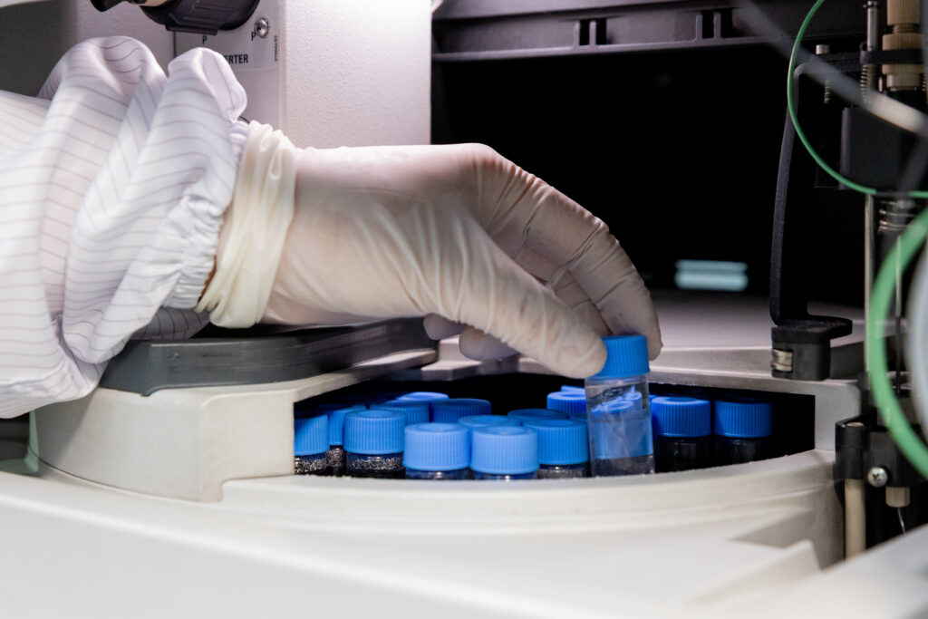
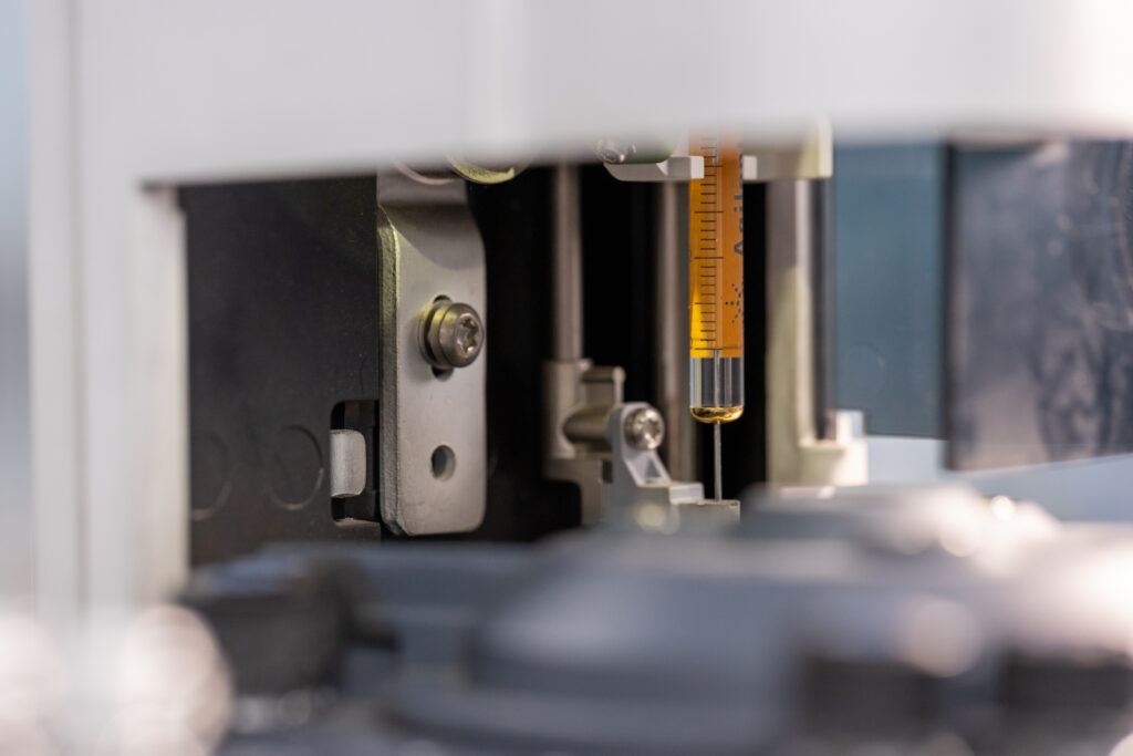
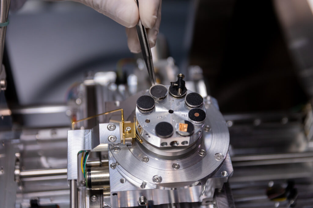
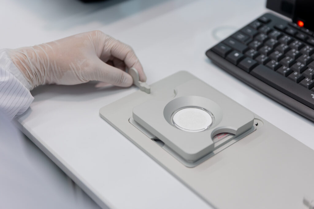
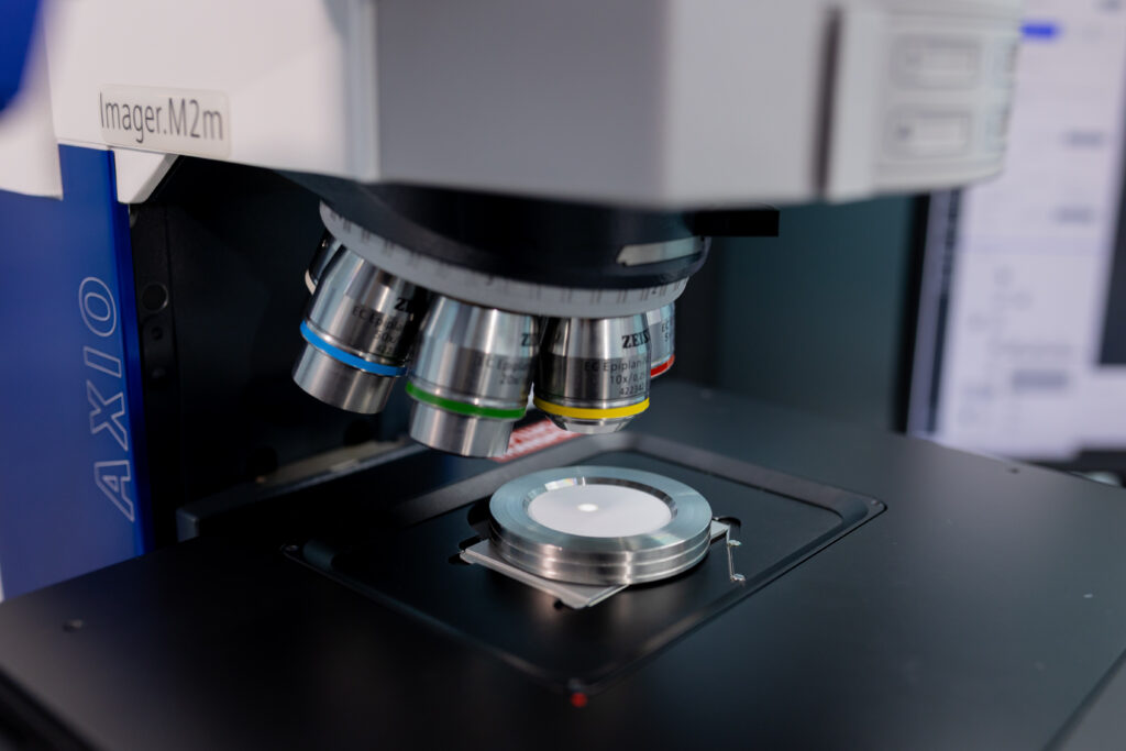
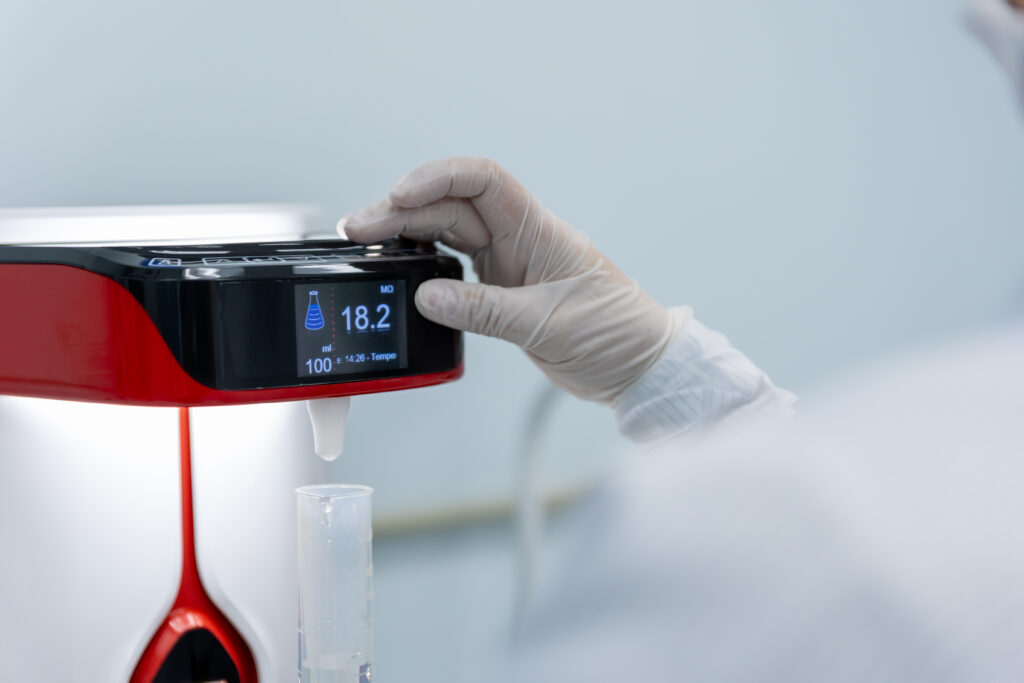
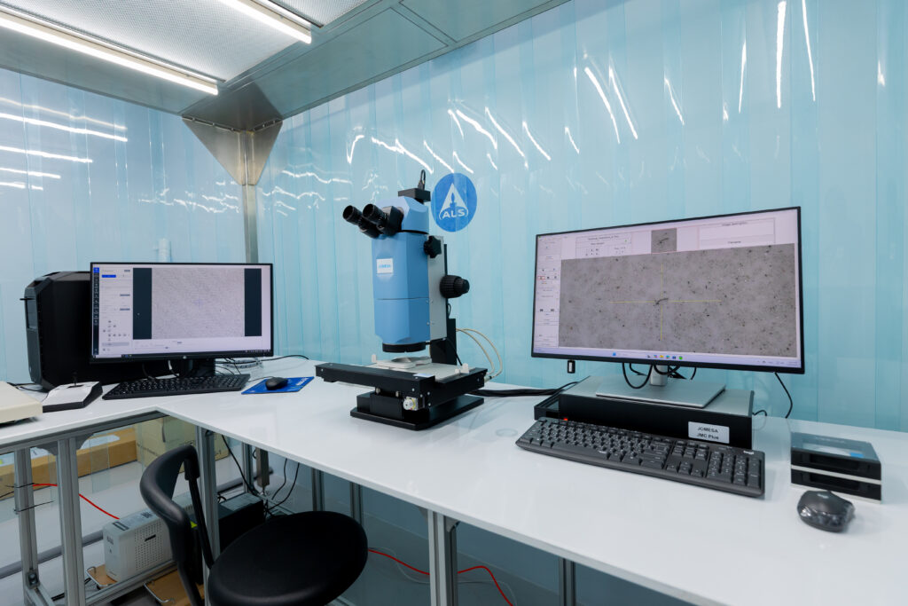
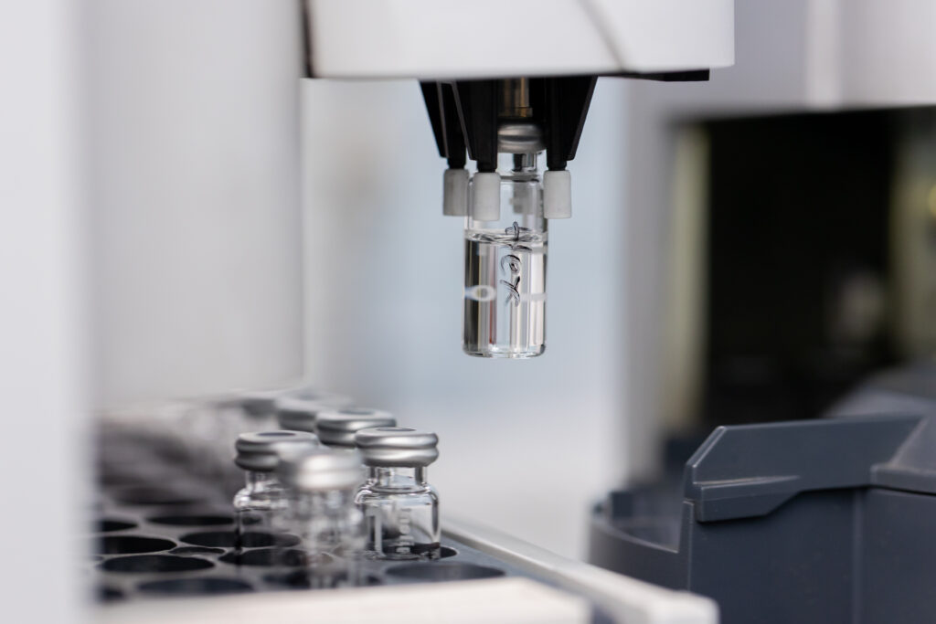
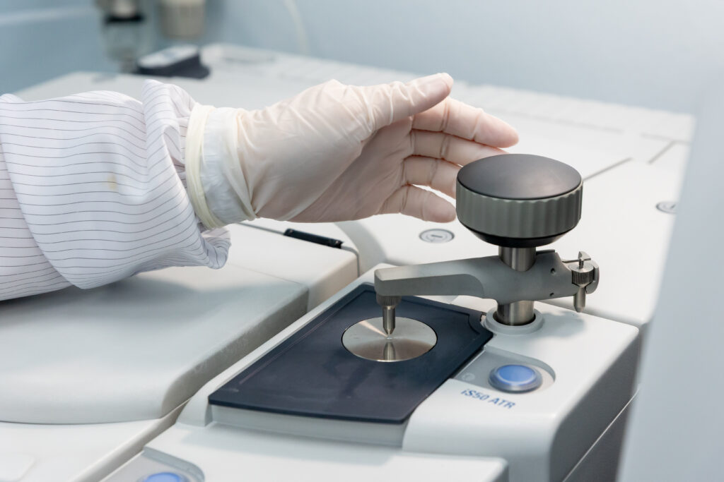
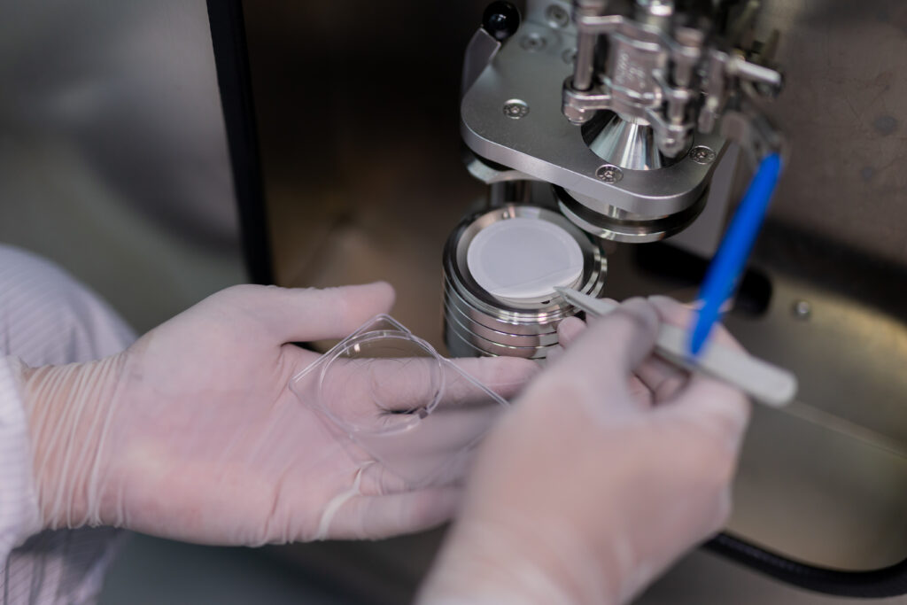
Particle Analysis · LPC Counting · Gravimetric Analysis · SEM Particle Identification
ISO/IEC 17025 Accredited | ISO 16232 & VDA 19 Specialist | SEM Particle ID Available
In precision automotive manufacturing, cleanliness is not a finishing step but a fundamental product specification. A single metallic particle of the wrong size in a hydraulic control valve, or a fibre contaminating a fuel injector channel, can translate into field failures, warranty claims, and production shutdowns that cost orders of magnitude more than the testing that would have prevented them.
Technical cleanliness testing – also known as component cleanliness testing or particle contamination analysis, is the validated process of extracting, quantifying, and characterising particulate contamination from the surfaces and internal channels of automotive components. It is governed by two internationally recognised standards: ISO 16232 (Road Vehicles – Cleanliness of Components) and VDA 19 (Testing of Technical Cleanliness – Particulate Contamination of Functionally Relevant Automotive Parts), the German automotive industry standard that is widely required by European OEMs.
ALS Testing is one of the very few independent laboratories in Malaysia and Southeast Asia offering ISO 16232 and VDA 19 cleanliness testing at specialist level. Our capability in this area represents a genuine competitive differentiator for our clients seeking OEM qualification, and for ALS as a laboratory in the regional market.
What Is Technical Cleanliness Testing?
Technical cleanliness testing is a structured analytical process that determines the type, size, and quantity of solid particulate contamination present in or on automotive components. It is applied to precision components where particle contamination poses a functional risk, primarily components with narrow channels, tight clearances, or surfaces that must maintain sealing integrity.
The process involves three core stages: particle extraction, particle quantification, and particle characterisation. Extraction removes particles from the component using a validated method, typically pressure flushing, ultrasonic agitation, or direct surface rinsing with a filtered solvent. Quantification determines the mass and number distribution of extracted particles. Characterisation identifies the morphology and, where required, the material composition of individual particles using microscopy and analytical techniques.
The output of a cleanliness test is a formal cleanliness class, expressed according to the ISO 16232 or VDA 19 classification system. This data allows manufacturers to verify compliance against their own internal specifications or OEM requirements.
Why Technical Cleanliness Matters for Automotive Manufacturers
The drive toward technical cleanliness in automotive manufacturing has been shaped by decades of field failure data linking particulate contamination to premature component failure. Hydraulic control systems in automatic transmissions, anti-lock braking systems, fuel injection systems, power steering units, and turbocharger oil supply circuits are all highly sensitive to particulate contamination. Even particles invisible to the naked eye (particles of 100 microns or less) can cause valve sticking, orifice blockage, accelerated wear, and seal damage.
For electric vehicle powertrains, the stakes are equally high. Battery thermal management systems, power electronics cooling circuits, and electric motor lubrication and cooling pathways all operate with close tolerances where contamination can cause insulation breakdown, thermal hotspots, or mechanical wear. As EV penetration grows in Southeast Asia, the demand for cleanliness testing of EV-specific components is growing alongside it.
OEM requirements for cleanliness compliance are increasingly contractual rather than advisory. Tier-1 suppliers to major European, Japanese, and American OEMs are routinely required to demonstrate cleanliness compliance using data from ISO/IEC 17025 accredited independent laboratories, not in-house testing. This is where ALS plays a critical role in the supply chain quality process.
ISO 16232 vs VDA 19: What Is the Difference?
ISO 16232 and VDA 19 are closely related standards, both governing the testing of technical cleanliness in automotive components. Understanding the relationship between them is important for specifying the correct test method.
Dimension
ISO 16232
VDA 19
Origin
International (ISO Technical Committee 22)
German Automotive Industry (VDA – Verband der Automobilindustrie)
Structure
10-part standard covering extraction, analysis, and reporting
Single comprehensive document – German and English versions
Adoption
Broadly adopted by global OEMs and regulatory frameworks
Required by German OEMs (BMW, Mercedes-Benz, Volkswagen Group, Bosch)
Particle Classes
Uses ISO cleanliness classes based on particle count per size range
Uses VDA cleanliness classes – more granular size range definition
Relationship
Harmonised – VDA 19 Part 1 and ISO 16232 are technically equivalent for most applications
VDA 19 Part 2 adds requirements for assembly environments
Reporting
ISO 16232 format – required for ISO-referencing OEM submissions
VDA 19 format – required for VDA-referencing OEM submissions
In practice, ALS tests to both standards, and our reports can be formatted to meet either ISO 16232 or VDA 19 reporting requirements depending on the OEM specification being addressed. When in doubt, our technical team will advise on the appropriate standard for your specific application.
Our Cleanliness Testing Services
ALS Testing offers a complete suite of technical cleanliness testing services, covering every stage of the analytical process from particle extraction through to SEM-based particle identification. All testing is conducted within our ISO/IEC 17025 accredited scope, with documented quality controls and traceability throughout.
Particle Extraction – Pressure Flush, Ultrasonic & Rinsing Methods
The foundation of any cleanliness test is the particle extraction method. ISO 16232 and VDA 19 define multiple validated extraction methods, each appropriate for different component geometries and contamination scenarios. ALS offers all primary extraction methods, selected in collaboration with the client based on the component design, functional surfaces of interest, and OEM specification requirements.
Pressure flushing is used for components with internal channels such as hydraulic valves, fittings, and manifolds, where a filtered solvent is flushed through under pressure to carry out particles. Ultrasonic extraction is applied to components where particles adhere to external or complex internal surfaces, using ultrasonic energy to dislodge them into a filtration medium. Rinsing extraction is a simpler method for relatively large components where surface contamination is the primary concern. All extraction solvents used are filtered to a level that ensures blank contamination remains below the defined threshold before component testing begins.
Gravimetric Analysis – Total Particle Mass
Gravimetric analysis determines the total mass of particles extracted from a component, expressed in milligrams. This provides a global contamination index that is compared against the mass-based cleanliness specification. The extracted particles are collected on a pre-weighed filter membrane, dried, and weighed on a calibrated analytical balance with traceability to national mass standards. Gravimetric analysis is a fundamental requirement of both ISO 16232 and VDA 19, and provides a clear quantitative index. This result is used by quality control teams to determine if a component meets the predefined mass-based limits for their specific production line.
Light Obscuration Particle Counting (LPC) – Size Distribution Analysis
Light obscuration particle counting (LPC), also known as automatic optical particle counting, provides a count of extracted particles distributed across defined size ranges, expressed as a particle size distribution. A laser-based instrument counts particles suspended in a clean solvent, recording both the total count and the count in each size class (typically 100–150 µm, 150–200 µm, 200–400 µm, 400–600 µm, 600–1000 µm, and >1000 µm). This data is used to assign an ISO 16232 or VDA 19 cleanliness class and to compare against the OEM-specified cleanliness requirement for the component.
LPC is the standard particle quantification method for ISO 16232 and VDA 19 cleanliness testing, and is required for any cleanliness class determination. It provides far more information than gravimetric analysis alone, enabling detection of large individual particles that may pose functional risk even when total particle mass is low.
Microscopic Particle Analysis & Classification
Following LPC, particles collected on the filter membrane are examined under a calibrated microscope (typically at 50x or 100x magnification) to classify individual particles by type, morphology, and size. ISO 16232 and VDA 19 define particle classification categories: metallic shiny (reflective metallic particles), metallic non-shiny (oxide-coated or corroded metals), fibres, and other non-metallic particles. This classification is important because different particle types carry different risk profiles; a metallic shiny particle of 400 µm in a hydraulic valve is far more concerning than a fibre of the same size.
Microscopic analysis is reported with representative photomicrographs of significant particles, providing visual evidence of the contamination types found. This information supports root cause investigation when cleanliness failures are identified.
SEM-EDX Particle Identification
For cases where the identity of individual particles must be confirmed, particularly in failure investigation, contamination source tracing, or where OEM specifications require elemental identification of particles exceeding a defined size. ALS offers scanning electron microscopy (SEM) with energy-dispersive X-ray spectroscopy (EDX) analysis of individual particles collected from the filter membrane.
SEM imaging provides high-magnification morphological characterisation of individual particles, while EDX provides elemental composition data that enables positive identification of particle material, for example distinguishing iron from aluminium from stainless steel, or identifying ceramic, glass, or polymer particle types. This combined SEM-EDX analysis is the most powerful particle identification tool available and provides definitive evidence for contamination source investigation.
Component Types We Test
ALS cleanliness testing services cover the full range of precision automotive components for which cleanliness specifications are typically defined by OEMs or international standards. Our experience spans hydraulic systems, powertrain components, fuel systems, braking systems, and EV-specific assemblies.
Hydraulic & Fluid Power Components
Hydraulic valves, valve bodies, manifolds, pump housings, cylinders, fittings, and tubing, all of which operate with fluid clearances where particulate contamination can cause sticking, jamming, or accelerated wear of precision-ground surfaces. ALS is experienced in testing components for automatic transmission hydraulic circuits, power steering systems, and industrial hydraulic assemblies to ISO 16232 and VDA 19 specifications.
Fuel System Components
Fuel injectors, fuel rails, fuel pumps, and direct injection components require extremely high cleanliness standards, as contamination can cause injector nozzle blockage, irregular spray patterns, and combustion chamber damage. Cleanliness requirements for high-pressure direct injection fuel systems are among the most stringent in automotive manufacturing, often requiring cleanliness classes that exclude particles above 100–200 µm.
Braking System Components
ABS modulators, brake calipers, master cylinders, and hydraulic brake lines must meet cleanliness specifications that protect the fine orifices and seal surfaces critical to braking system integrity. ALS tests braking components to OEM cleanliness specifications and ISO 16232, with particular attention to metallic particle counts that indicate machining residue or wear debris.
EV & Powertrain Components
Electric motor housings, battery thermal management circuit components, power electronics cooling plate assemblies, and EV gearbox components all require cleanliness verification as EV production scales up across the region. ALS is developing and applying cleanliness testing protocols for EV-specific components, drawing on our ISO 16232 expertise and engaging with emerging OEM specifications for EV powertrain cleanliness.
Standards & Test Methods
Our cleanliness testing is conducted to the following primary standards and test methods, all within our ISO/IEC 17025:2017 accredited scope. For tests outside our accredited scope, we apply validated in-house methods following the principles and protocols established by ISO 16232 and VDA 19.
Standard / Method
Description
Application
ISO 16232
Road Vehicles – Cleanliness of Components (10 parts)
International cleanliness standard for all automotive components
VDA 19 Part 1
Testing of Technical Cleanliness – Particle Contamination Analysis
German OEM requirement – BMW, VW Group, Mercedes-Benz, Bosch
VDA 19 Part 2
Assembly Environment Requirements for Technical Cleanliness
Clean area requirements for assembly processes
Gravimetric Analysis
Total extracted particle mass by calibrated weighing
Quantitative mass measurement for comparison against customer-defined limits.
Light Obscuration Particle Counting (LPC)
Automated particle count by size class using laser obscuration
Particle size distribution – ISO/VDA cleanliness class assignment
Microscopic Particle Classification
Manual classification of particles by type and morphology
Particle type distribution – metallic, fibre, non-metallic
SEM-EDX Particle ID
SEM imaging + elemental analysis of individual particles
Particle source identification, failure investigation, OEM requirement
Why Choose ALS for Cleanliness Testing?
Technical cleanliness testing is a specialised capability that requires more than a particle counter and a filter membrane. It requires experienced analysts who understand automotive manufacturing processes, validated extraction methods appropriate to the component type, calibrated equipment with documented traceability, and a quality management system that ensures the reliability of every result.
One of Very Few Specialists in Malaysia & SEA
ALS is one of very few independent laboratories in Malaysia and Southeast Asia offering ISO 16232 and VDA 19 cleanliness testing at this level of depth. While general testing laboratories may offer particle counting services, the full cleanliness testing process, including validated extraction, gravimetric analysis, LPC, microscopic classification, and SEM-EDX particle identification, which requires specific expertise and investment that ALS has made and maintains.
Full Process Capability from Extraction to SEM-EDX
Unlike laboratories that offer only partial cleanliness testing capability, ALS provides the complete analytical workflow from sample reception and extraction method selection through to final report with SEM-EDX particle identification where required. This full-process capability means that you can manage your entire cleanliness testing requirement through a single laboratory relationship, with consistent methods and results across all your components and platforms.
ISO/IEC 17025 Accredited Results
Our ISO/IEC 17025:2017 accreditation covers cleanliness testing within our accredited scope, meaning that our results carry the formal weight of internationally recognised laboratory accreditation. For OEM submissions and qualification programmes that require accredited test data, ALS test reports satisfy this requirement without question.
Frequently Asked Questions – Cleanliness Testing
Q: What is technical cleanliness testing and why do automotive OEMs require it?
Technical cleanliness testing is the validated process of extracting, quantifying, and characterising particulate contamination from automotive components. OEMs require it because particulate contamination in precision components, particularly hydraulic systems, fuel systems, and braking systems, is a leading cause of field failures and warranty claims. ISO 16232 and VDA 19 provide the standardised framework for cleanliness specification and verification, and OEMs contractually require Tier-1 suppliers to demonstrate compliance using data from accredited independent laboratories.
Q: What is the difference between ISO 16232 and VDA 19?
ISO 16232 is the international standard for automotive component cleanliness testing, developed by ISO Technical Committee 22. VDA 19 is the German automotive industry standard, developed by the VDA (German Association of the Automotive Industry), and is specifically required by German OEMs such as BMW, Volkswagen Group, and Mercedes-Benz, and their major suppliers. The two standards are harmonised: VDA 19 Part 1 is technically aligned with ISO 16232, but the reporting formats and classification systems differ. ALS can test to either standard and can format reports to meet your specific OEM submission requirement.
Q: What types of particles are identified in a cleanliness test?
ISO 16232 and VDA 19 define four primary particle types: metallic shiny particles (highly reflective metals such as machined steel or aluminium), metallic non-shiny particles (oxide-coated or corroded metals, cast particles), fibres (organic or synthetic fibres from wipes, clothing, or seals), and other non-metallic particles (rubber, ceramic, glass, polymer). SEM-EDX analysis can further identify the elemental composition of individual particles for definitive material identification.
Q: How do I prepare my components for cleanliness testing submission?
Component preparation and packaging are important to avoid contamination between manufacturing and laboratory testing. In general, components should be sealed in clean polythene bags immediately after manufacture and kept sealed until sample submission. Do not use paper or cardboard packaging in contact with the component surface. Please contact our team before submission and we will provide specific sample packaging and shipping instructions for your component type.
Q: Can ALS test to OEM-specific cleanliness specifications?
Yes. ALS has experience with a range of OEM-specific cleanliness specifications in addition to the ISO 16232 and VDA 19 standards. Please provide the OEM specification document number and revision when making your enquiry, and our technical team will confirm our capability and advise on the test programme required.
Request a Cleanliness Testing Quote
Whether you are seeking ISO 16232 certification for a new component programme, investigating a cleanliness-related field failure, or establishing a cleanliness testing protocol for a new product line, ALS Testing has the expertise and accreditation to support you. Contact our team today to discuss your requirements and receive a quotation.
→ Request a Quote: https://www.alstesting.co.th/request-a-quote/
→ Back to Automotive Testing Hub: /automotive-testing/
ISO/IEC 17025 Accredited | ISO 16232 & VDA 19 Specialist | SEM-EDX Particle ID Available
Read more