
Promotion
- โชว์สินค้าทั้งหมด
- No categories
May 14, 2026
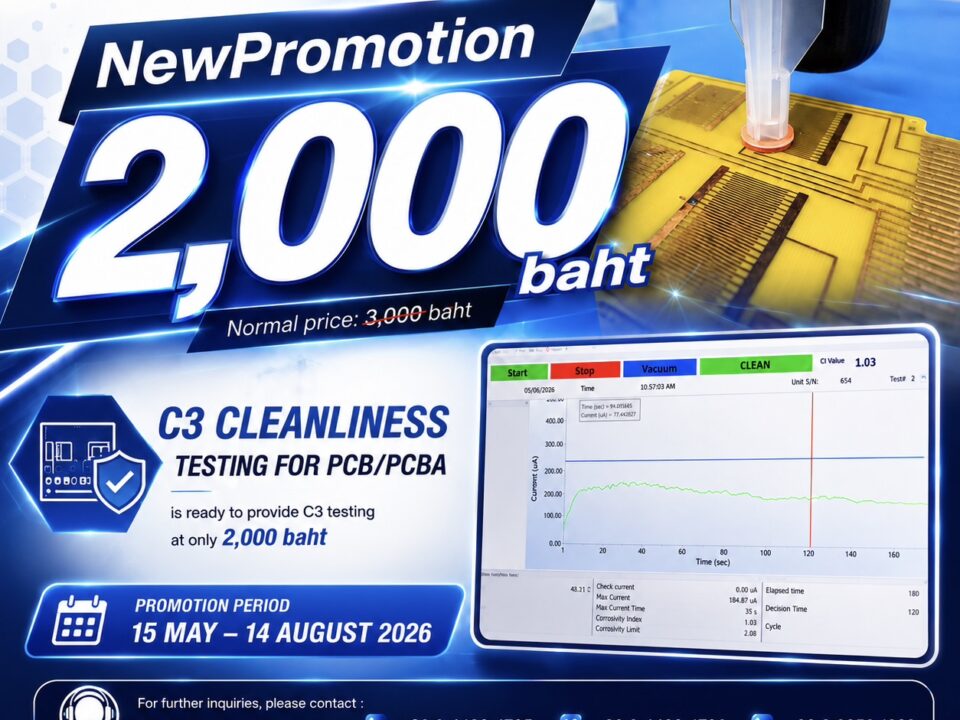
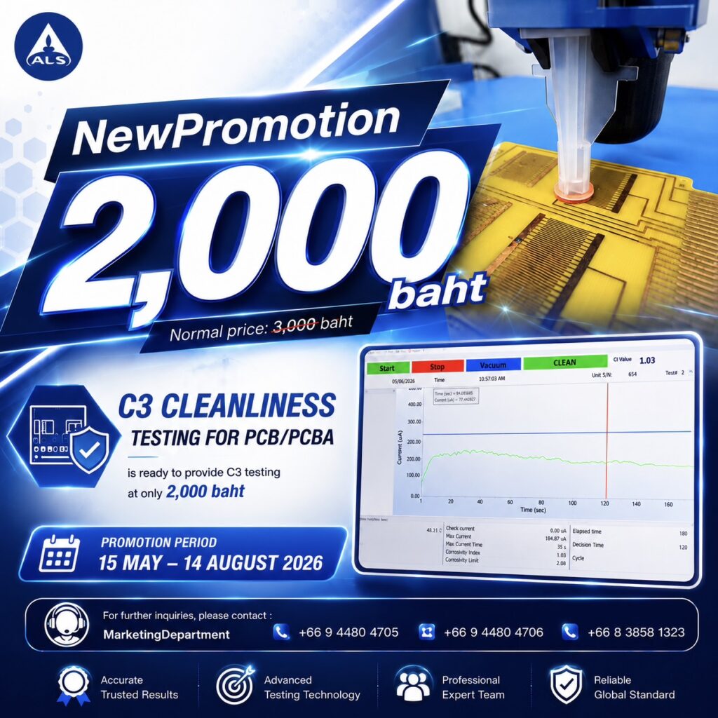
C3 (Critical Cleanliness Control®) — The Next Level of PCB Cleanliness Testing
ALS Testing Services (Thailand) Co., Ltd.
New Service
Special Offer : 2,000 baht
(Regular Price: 3,000 baht)
️ Promotional Details — Limited Time Offer
ALS is proud to offer C3 testing at a special introductory price:
Regular Price
Promotional Price
C3 Testing Service
฿3,000
✅ ฿2,000
️ Promotion Period: May 15 – August 14, 2026 (Limited-time offer — secure your slots early!)
The Hidden Threat on Every PCB
In today’s electronics manufacturing landscape, cleanliness is not just a matter of aesthetics — it is a fundamental quality and reliability requirement. Every printed circuit board (PCB) that passes through a production line is exposed to a wide range of potential contaminants: flux residues, ionic salts, process chemicals, airborne particulates, moisture, and even fingerprint oils from human handling.
What makes this especially dangerous is that many of these contaminants are invisible to the naked eye. A PCB may look perfectly clean under normal inspection — yet still carry enough ionic contamination to cause field failures months or years down the line.
The consequences of neglecting PCB cleanliness can be severe:
️ Moisture absorption by residual ionic salts
⚙️ Electrochemical corrosion of copper traces and solder joints
️ Electromigration and dendritic growth — microscopic conductive bridges forming between circuit traces
⚡ Leakage currents and short circuits
Complete board failure — often unpredictable and difficult to trace in the field
This is why cleanliness testing is no longer optional — it is a critical step in any robust quality assurance and reliability program.
What Is C3 (Critical Cleanliness Control®)?
C3 (Critical Cleanliness Control®) is a state-of-the-art, localized ionic cleanliness testing technology designed specifically to address the limitations of traditional cleanliness measurement methods.
At its core, C3 works by using ultra-pure deionized water as an extraction medium. A precisely controlled volume of water is applied to a specific, targeted area of the PCB surface. The water extracts ionic contaminants from that localized zone, and the resulting solution is then analyzed by measuring its electrical conductivity and resistance. From these measurements, the instrument calculates the Corrosivity Index (C.I.) — a standardized indicator of contamination level and potential corrosion risk.
The fundamental principle is elegant in its simplicity:
The more ionic contamination present, the higher the electrical conductivity of the extract → the higher the C.I. value → the greater the risk.
Conversely:
✅ Low C.I. = Clean PCB = Low corrosion risk = Reliable product
The Science Behind Ionic Contamination
To fully appreciate the value of C3 testing, it is important to understand why ionic contamination is so harmful at a fundamental level.
What Are Ionic Contaminants?
Ionic contaminants are electrically charged chemical species (ions) — both positively charged cations (e.g., Na⁺, K⁺, Ca²⁺) and negatively charged anions (e.g., Cl⁻, Br⁻, SO₄²⁻) — that remain on the PCB surface after manufacturing.
Common sources include:
Contamination Source
Typical Ionic Species
Solder flux residues
Organic acids, halide activators (Cl⁻, Br⁻)
Human handling
NaCl (sodium chloride) from perspiration
Process water
Calcium, magnesium, chloride ions
Atmospheric dust
Mixed ionic salts
Cleaning agent residues
Surfactant ions, alkaline species
PCB substrate outgassing
Various organic ionic compounds
⚠️ The Electrochemical Failure Mechanism
When ionic contaminants combine with moisture — even at normal ambient humidity levels — they form a thin electrolytic film on the PCB surface. In the presence of an applied electric field (i.e., a powered circuit), this sets off a chain of electrochemical reactions:
Ionic contamination+H2O+Electric field→Electrochemical corrosion+Dendritic growthIonic contamination+H2O+Electric field→Electrochemical corrosion+Dendritic growth
Dendritic growth (also called electrochemical migration or ECM) is particularly insidious: metallic ions dissolved from corroding conductors are redeposited as branching, tree-like conductive filaments that can bridge adjacent circuit traces, causing intermittent or permanent short circuits. These failures are notoriously difficult to diagnose after the fact.
Traditional Testing vs. C3 — Understanding the Difference
❌ Traditional Methods: ROSE Testing (Resistivity of Solvent Extract)
For decades, the industry relied primarily on ROSE (Resistivity of Solvent Extract) testing — standardized under IPC-TM-650 Method 2.3.25 — as the go-to cleanliness measurement. In ROSE testing, the entire PCB is immersed in a mixture of isopropyl alcohol (IPA) and deionized water, and the total ionic contamination of the whole board is measured.
While ROSE testing provides a useful global cleanliness benchmark, it has well-recognized limitations:
❌ It gives only a board-average result — it cannot identify where contamination is located
❌ High-risk localized zones (e.g., beneath dense IC packages) may have dangerous contamination levels that are diluted and masked by cleaner areas elsewhere on the board
❌ It cannot be performed on boards with components or coatings already applied
❌ Results are not spatially resolved — they provide no actionable guidance for process engineers
✅ C3: The Localized, Targeted Solution
C3 was developed precisely to overcome these limitations. Rather than flooding the entire board, C3 applies its extraction water to a precisely defined, small area — as small as a few square centimeters — enabling point-by-point contamination mapping of the PCB surface.
Feature
ROSE / Traditional Testing
C3 (Critical Cleanliness Control®)
Testing Area
Entire board (global average)
Specific localized zones
Spatial Resolution
None
High — point-by-point mapping
Under-component testing
❌ Not possible
✅ Capable (QFN, BGA, etc.)
Non-destructive
✅ Yes
✅ Yes
Speed
Moderate
⚡ Rapid — near-immediate results
Process trend monitoring
Limited
✅ Full C.I. trend tracking
Actionability
Low
High — identifies specific problem areas
Key Advantages of C3 Testing
1. Localized, Targeted Testing
Unlike global testing methods, C3 allows engineers to test exactly where it matters most — directly beneath high-density IC packages, in solder joint crevices, around connector interfaces, or any zone identified as high-risk. This targeted approach dramatically increases the sensitivity and relevance of the contamination data.
2. ⚡ Rapid, Real-Time Results
C3 delivers results almost immediately after sample extraction. This makes it ideal for in-line or at-line quality control, enabling rapid feedback during production rather than waiting for lengthy laboratory turnaround times.
3. Fully Non-Destructive
The C3 extraction process uses only ultra-pure water and causes zero physical or electrical damage to the PCB, its components, solder joints, or surface finishes. The tested board can proceed normally through the production process or be returned to the customer without any impact on its integrity.
4. Process Trend Monitoring and SPC Integration
Because C3 generates quantitative C.I. data for specific locations, it is perfectly suited to Statistical Process Control (SPC) integration. Engineers can plot C.I. values over time to:
Identify process drift before it causes failures
Evaluate the effectiveness of cleaning process changes
Establish and maintain cleanliness control limits
Generate compliance documentation for customers and auditors
5. Hidden Zone Inspection (Under-Component Testing)
One of the most powerful capabilities of C3 is its ability to assess contamination beneath components — including low-standoff packages such as QFN (Quad Flat No-Lead) and BGA (Ball Grid Array) devices, where conventional inspection is physically impossible. This is increasingly critical as component miniaturization continues and the standoff gap between package and PCB becomes ever smaller.
Applications Across the Electronics Manufacturing Lifecycle
C3 is a versatile tool applicable at multiple stages of PCB fabrication, assembly, and quality assurance:
✔️ 1. Post-Soldering Cleanliness Verification
After wave soldering, reflow soldering, or selective soldering operations, flux residues — especially from no-clean flux formulations — may remain on the PCB surface. C3 provides a quantitative measure of residual ionic contamination, enabling engineers to determine whether cleaning is required or whether the no-clean residues are within acceptable limits.
✔️ 2. Pre-Conformal Coating Inspection
Conformal coating is applied to protect PCBs in harsh environments (humidity, chemicals, vibration). However, if ionic contamination is present beneath the coating, moisture can penetrate and trigger under-coating corrosion and delamination, causing the coating to fail. C3 testing before coating application ensures that the substrate is clean and that the coating will perform as intended.
✔️ 3. In-Line Production Quality Control
C3 can be integrated into the production quality control workflow as a routine check at defined process stages. By monitoring C.I. values at regular intervals, manufacturing teams can maintain consistent cleanliness standards and rapidly detect when a process step (e.g., a solder paste applicator, a flux dispensing system, or a cleaning machine) begins to drift out of specification.
✔️ 4. PCB Failure Analysis (FA)
When a PCB is returned from the field due to a reliability failure, C3 is an invaluable tool in the failure analysis process. By mapping the contamination profile of specific areas on the failed board — and comparing it against reference (non-failed) boards — engineers can determine whether ionic contamination played a role in the failure and identify its likely source.
✔️ 5. Cleaning Process Validation and Optimization
When introducing or validating a new cleaning chemistry, cleaning machine, or cleaning process parameter, C3 provides the quantitative data needed to confirm that the process effectively removes contamination from all critical zones, including those beneath low-standoff components.
✔️ 6. Incoming Material and Bare Board Inspection
C3 can also be applied to bare PCB substrates and incoming solder paste or flux materials to verify their ionic contamination levels before they enter the production line — preventing contamination from being introduced at the very start of the manufacturing process.
Understanding the Corrosivity Index (C.I.)
The primary output of C3 testing is the Corrosivity Index (C.I.), a dimensionless numerical value derived from the electrical conductivity measurement of the extraction solution. The C.I. provides a direct, standardized, and comparable measure of ionic contamination for any tested location.
C.I. Interpretation Guide:
C.I. Value Range
Cleanliness Status
Risk Level
Recommended Action
Low ✅
Excellent — PCB is clean
Very Low
No action required; approve for next process
Moderate ⚠️
Acceptable — minor contamination
Low–Medium
Monitor trend; review process
High ❌
Contamination detected
High
Investigate source; consider re-cleaning
Very High ❌❌
Heavy contamination
Critical
Do not proceed; immediate corrective action
Note: Specific C.I. acceptance thresholds should be established based on the end-use application, customer requirements, and applicable industry standards (e.g., IPC-7711/7721, IPC-6012, IPC-A-610).
Industry Standards and Regulatory Context
The importance of PCB cleanliness is recognized and mandated by major international electronics industry standards:
IPC-7711/7721 — Rework, Modification and Repair of Electronic Assemblies
IPC-6012 — Qualification and Performance Specification for Rigid Printed Boards
IPC-A-610 — Acceptability of Electronic Assemblies
IPC-TM-650 2.3.25 — Ionic Cleanliness Testing
J-STD-001 — Requirements for Soldering Electrical and Electronic Assemblies
MIL-PRF-31032 / MIL-P-55110 — Military specifications for PCB reliability
C3 testing supports compliance with these standards by providing the localized, quantitative, and traceable cleanliness data that global testing methods cannot supply.
Contact Us
For inquiries, quotations, and sample submissions, please contact our Marketing Team:
+66 94 480 4705 +66 94 480 4706 +66 83 858 1323
➡️ Click here to view full promotion details
Read moreJuly 2, 2024
February 8, 2024
