
Scanning Electron Microscopy Analysis for Failure Analysis: SEM, FTIR, Cross-Section and Root Cause Investigation

Automotive Testing Standards ISO, VDA, IEC and ASTM Complete Reference Guide
June 30, 2026Scanning Electron Microscopy Analysis for Failure Analysis: SEM, FTIR, Cross-Section and Root Cause Investigation
SEM · EDX · FTIR · Cross-Sectioning · Root Cause Investigation
ISO/IEC 17025 Accredited Testing Where Applicable | SEM EDX FTIR Cross-Section Support | Automotive Failure Analysis
A component can fail in many ways. It may crack during qualification testing, return from the field with corrosion, show a coating defect, or fail electrically without an obvious surface mark. The first question is usually what failed. The more useful question is why it failed.
Scanning electron microscopy analysis is one of the key techniques used in automotive failure investigation because it can examine fracture surfaces, corrosion features, particles, coatings and surface defects at much higher magnification than optical microscopy. It is rarely used alone. A stronger investigation usually combines SEM with EDX, FTIR, cross-sectioning and background information from the component’s service or production history.
A good failure analysis does not jump straight to the highest magnification. It starts with the least destructive checks, builds evidence step by step, and only cuts or alters the sample when the investigation has a clear reason to do so.
What Happens During Failure Analysis
Failure analysis is a structured investigation used to understand the physical, chemical or mechanical evidence behind a component failure. The aim is not simply to take microscope images. The aim is to connect the observed damage with the most likely failure mechanism and the conditions that caused it.
A typical investigation moves from broad observation to targeted analysis.
| Stage | What it does | Why it matters |
| Visual and optical examination | Documents the sample as received and locates the failure area | Preserves evidence before cutting, cleaning or coating |
| SEM imaging | Examines fracture surfaces, corrosion, particles or surface defects at high magnification | Shows fine surface features that optical microscopy may miss |
| EDX analysis | Detects elemental signals from selected areas or particles | Supports material, contamination or corrosion hypotheses |
| FTIR spectroscopy | Identifies organic materials such as polymers, oils, coatings or residues | Useful for non-metallic contamination and polymer-related failures |
| Cross-sectioning | Cuts and polishes the sample to reveal internal structure | Shows coating layers, interfaces, crack paths, porosity or solder joint features |
The order can change depending on the sample, but the principle is the same. Non-destructive documentation should come first. Destructive preparation should come later, once the analyst knows what evidence needs to be exposed.
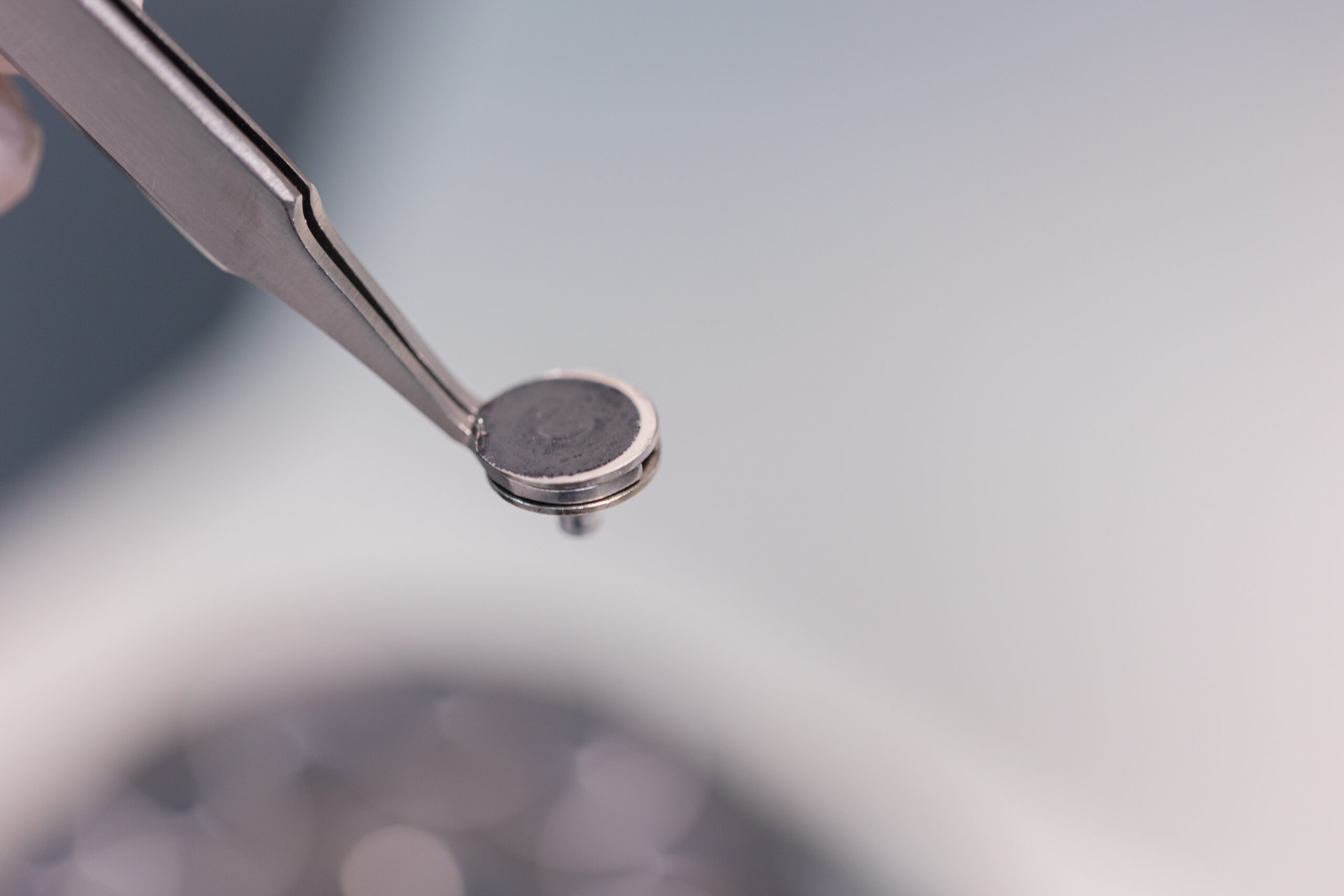
Visual and Optical Examination
The first stage is simple but important. The laboratory documents the sample condition, photographs the failure area and records visible features such as cracks, corrosion, staining, deformation, wear marks or coating damage.
Stereo microscopy gives a low magnification overview with depth of field. This helps the analyst decide where to examine next with SEM or where a cross-section should be taken. Skipping this stage can remove context that may be needed later, especially if the sample is cut, cleaned or mounted.
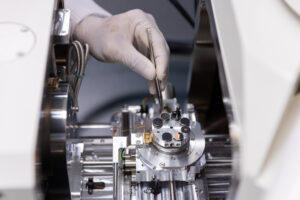
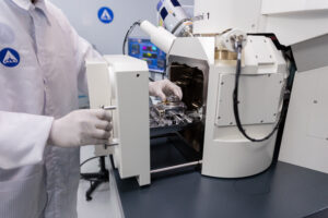
Scanning Electron Microscopy Analysis
SEM uses a focused electron beam to scan the sample surface and create high magnification images. In failure analysis, this is especially useful for fracture surfaces and rough three-dimensional features.
On a broken metal part, SEM may show features that support a fatigue, overload, brittle fracture or wear-related interpretation. Fatigue striations, where present, can indicate progressive crack growth. Dimpled features may support ductile overload. Cleavage-like facets may support brittle fracture. These features are not interpreted in isolation; they must be considered with material, loading history, geometry and service conditions.
SEM is also useful for corrosion deposits, coating defects, particles, contamination and surface damage. It can show morphology clearly, but it does not identify every chemical compound by itself. That is why SEM is often paired with EDX.

What EDX Adds to SEM
EDX, also written as EDS, detects characteristic X-rays emitted from the sample when it is examined under the electron beam. This allows the analyst to identify elements present in a selected point, area or particle.
For example, EDX may detect chlorine, sulfur, oxygen, iron, aluminium, copper, silicon or other elemental signals. These signals can support a corrosion, contamination or material transfer hypothesis. However, EDX should not be described as confirming a specific compound on its own. Detecting chlorine does not automatically prove a defined chloride compound, and detecting sulfur does not automatically prove sulfate. The result needs to be interpreted with the sample condition, morphology and any supporting tests.
FTIR for Organic Materials and Residues
SEM and EDX are strong tools for imaging and elemental analysis, but they are not the best choice for identifying organic materials. FTIR is used when the question involves polymers, coatings, adhesives, oils, elastomers or residue films.
FTIR measures how a material absorbs infrared light and produces a spectrum that can be compared with reference data. In automotive failure analysis, FTIR may help identify a seal material, a polymer contaminant, an adhesive residue, a coating film or degraded organic material found near the failure area.
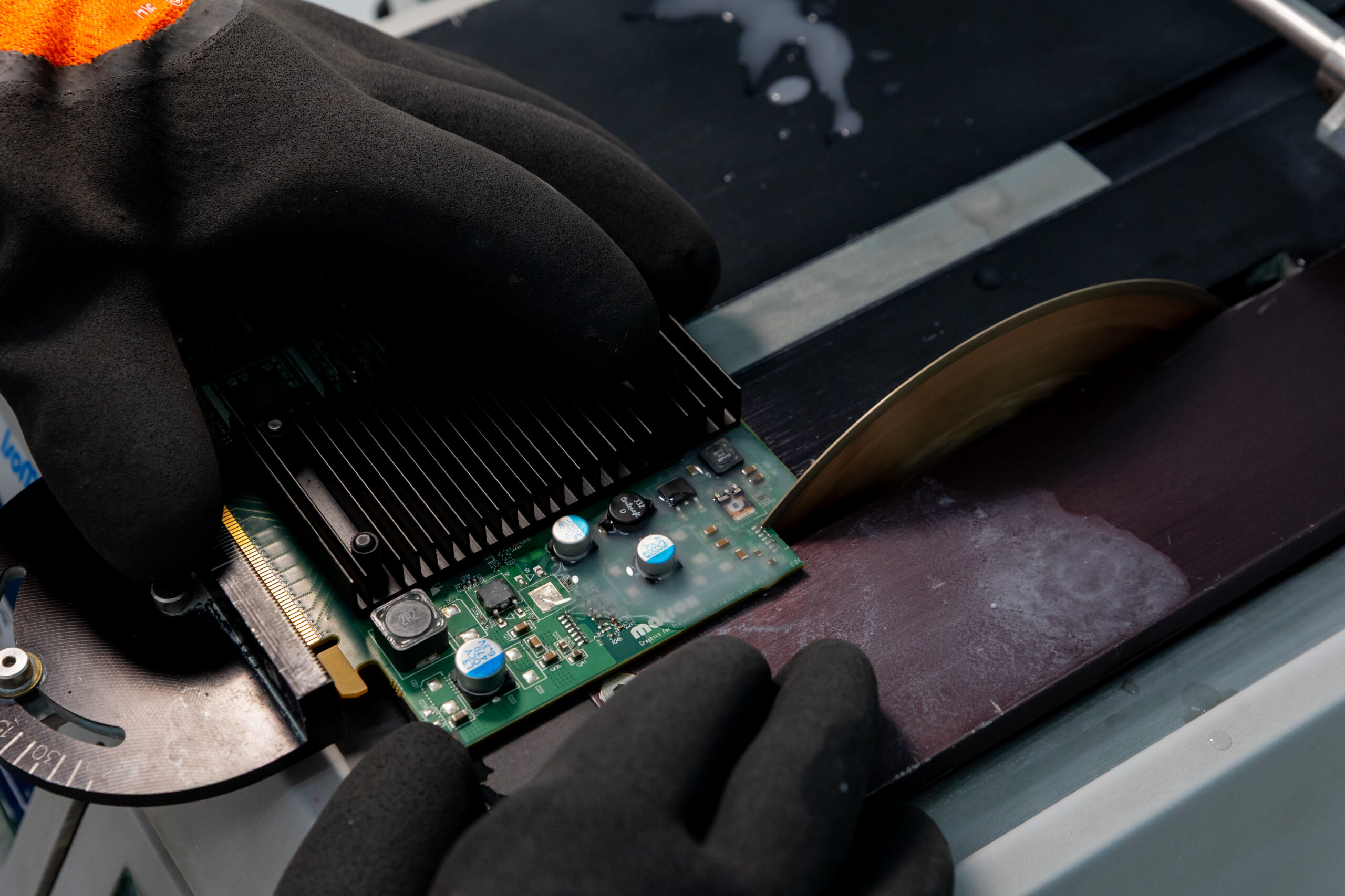
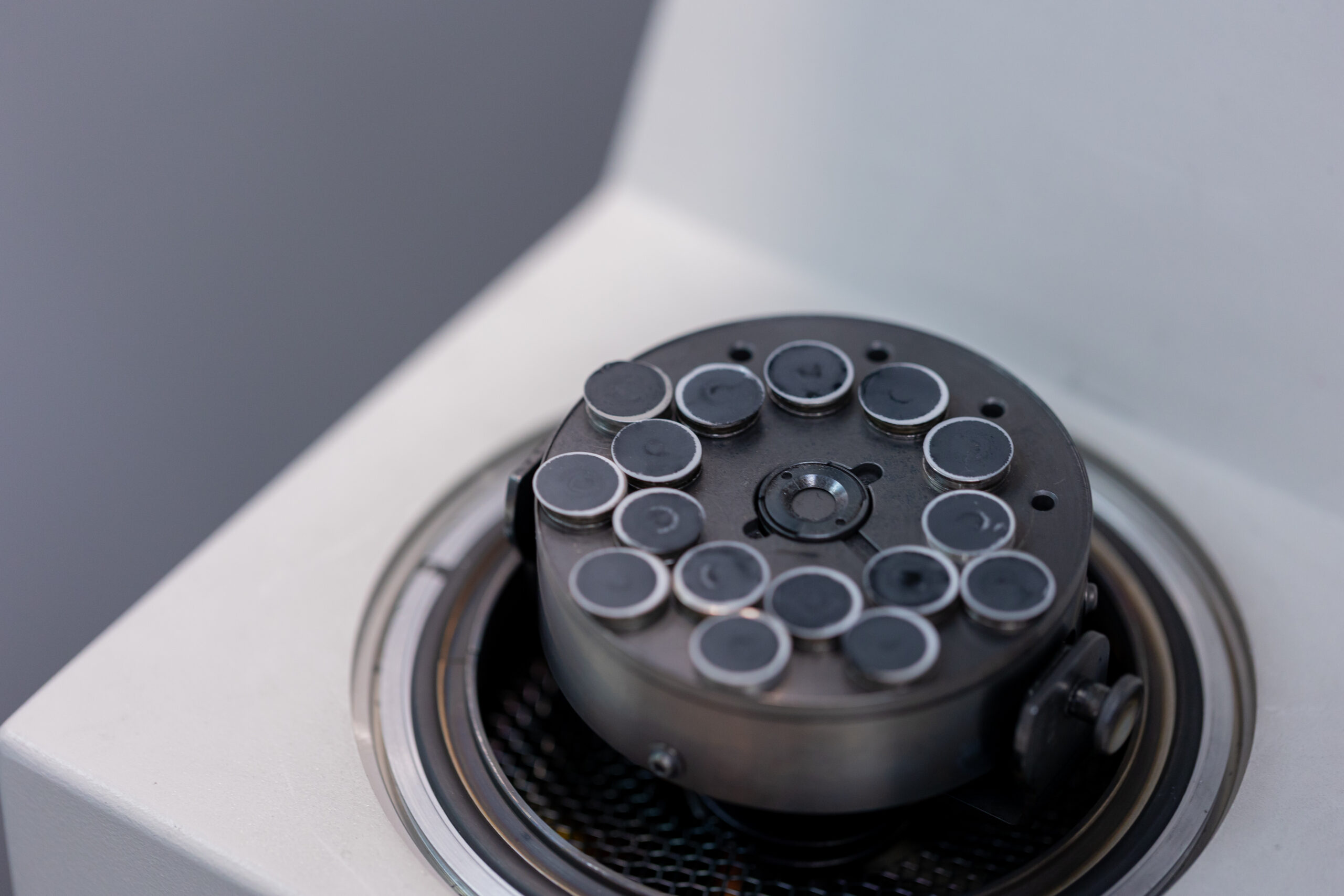
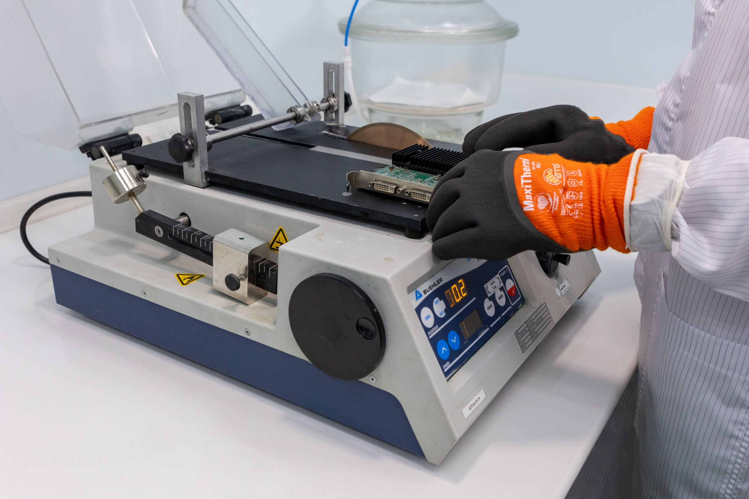
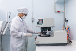
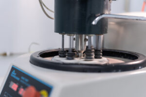
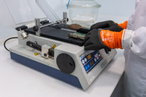
Cross-Section Analysis
Some failures cannot be understood from the surface. Cross-section analysis is used when the investigation needs to see inside the material, coating, solder joint, plated layer or bonded interface.
The sample is mounted, cut, ground and polished to expose the area of interest. In metals, etching may be used to reveal microstructure. In coatings or electronics, the cross-section can show layer thickness, voids, cracks, delamination, porosity or interface defects.
Because cross-sectioning permanently changes the sample, it should be performed after visual and surface examination. The cut location should be chosen based on the evidence already collected.
Which Technique Fits Which Failure
Different failure symptoms need different evidence. The table below gives a practical starting point, but the final test plan should be based on the sample condition and investigation objective.
| Failure symptom | Useful techniques | Evidence the laboratory may look for |
| Cracked metal component | Visual exam, SEM, EDX, cross-sectioning | Crack origin, fracture mode, inclusions, corrosion or overload features |
| Corroded connector | Visual exam, SEM, EDX, FTIR where residue is present | Corrosion morphology, elemental signals, residue or film identification |
| Coating defect | Optical exam, cross-sectioning, SEM, FTIR | Coating thickness, adhesion issue, contamination, interface condition |
| Polymer or rubber failure | FTIR, optical exam, SEM where needed | Material identification, degradation, contamination or surface damage |
| Unknown particles or residue | SEM-EDX, FTIR | Elemental profile, organic material type or possible contamination source |
A single technique may answer part of the issue, but most root cause work needs multiple evidence streams. SEM can show how a surface failed. EDX can add elemental information. FTIR can identify organic residue. Cross-sectioning can show what happened below the surface.
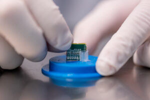
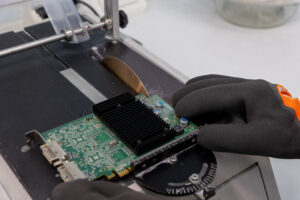
Example Investigation
Consider an automotive connector returned from the field after intermittent electrical failure. Visual examination may show staining around the contact area. SEM can examine the contact surface at higher magnification and show corrosion morphology or particles between contacts. EDX can detect elemental signals such as chlorine, sulfur, copper, tin or other elements that support a contamination or corrosion hypothesis.
If a film or residue is present, FTIR may help identify whether it is an oil, polymer, adhesive residue or process-related organic material. If moisture ingress or seal failure is suspected, a cross-section through the sealing area can show whether the interface, seal geometry or housing condition contributed to the failure.
The conclusion should be based on all of the evidence, not on one image or one spectrum alone.
What to Prepare Before Sending a Sample
Failure analysis is more focused when the laboratory receives both the failed part and the right background information. Prepare the following where available.
- Component name and function
- Failure symptom and when it was discovered
- Whether the sample came from production, qualification testing or the field
- Material grade, coating, plating or surface treatment
- Operating environment such as heat, humidity, vibration or chemical exposure
- Number of failed samples and number of good comparison samples
- Photos before removal or cleaning, if available
- Any previous test data or inspection records
- What decision the report needs to support, such as root cause, corrective action or customer response
Avoid cleaning, cutting or altering the failed area before submission unless the laboratory advises it. If comparison samples are available, include them. A good part from the same lot can make the investigation much stronger.
What a Failure Analysis Report Can and Cannot Do
A failure analysis report can identify observed damage, describe the evidence, explain the likely failure mechanism and support an evidence-based root cause conclusion. In many cases, it can also suggest contributing factors or recommend what process area should be checked next.
It should not be treated as a legal judgement by itself. Whether the root cause becomes supplier responsibility, design issue, production escape, misuse or field exposure depends on technical evidence plus contractual and commercial context.
Turnaround time also depends on scope. A simple SEM-EDX examination may be faster than a multi-technique investigation involving cross-section preparation, FTIR and comparison samples. If the case is urgent, the timing should be discussed before the test plan is confirmed.
Frequently Asked Questions
Do I need to know which technique I need before contacting a laboratory
No. You can send the failure description, photos and available background information first. The laboratory can recommend whether SEM, EDX, FTIR, cross-sectioning or another method is appropriate.
What is scanning electron microscopy analysis used for
Scanning electron microscopy analysis is used to examine fine surface features such as fracture morphology, corrosion deposits, wear marks, particles, coating defects and contamination. It helps show details that are not visible with normal optical microscopy.
Can SEM and EDX identify the exact cause of corrosion
They can support a corrosion investigation by showing morphology and elemental signals. They may indicate the presence of elements such as chlorine, sulfur or oxygen. The exact cause still depends on supporting evidence such as service history, material condition, environment, residue analysis and process data.
Is failure analysis only for metal components
No. Failure analysis can be applied to metals, polymers, rubber, coatings, adhesives, electronics materials and composites. The technique selection depends on the material and the failure symptom.
Is every failure analysis result covered by ISO/IEC 17025 accreditation
Not necessarily. ISO/IEC 17025 accreditation applies to specific methods within a laboratory’s accredited scope. If accredited results are required for submission, confirm the exact method and scope before testing begins.
Go Deeper into SEM Analysis
This article explains SEM as part of a broader failure analysis workflow. For a more detailed technical guide to SEM imaging, magnification, sample preparation and limitations, read the dedicated SEM Analysis for Automotive Failure Investigation article.
Request a Failure Analysis Quote
ALS Testing can support automotive failure analysis for cracked components, corrosion, coating defects, contamination, polymer issues and field-returned assemblies.
Testing under ISO/IEC 17025 accreditation is available where covered by the applicable accredited scope. Share the sample condition, failure background and required report purpose so the laboratory can recommend the right investigation plan.
Next Steps
- Back to Failure Analysis Hub for the full service overview at https://www.alstesting.co.th/failure-analysis-services-sem-ftir-edx-als-testing/
- Read the detailed SEM Analysis guide for automotive failure investigation
- Explore FTIR material identification capabilities for automotive materials
- Contact our team to discuss a failure analysis investigation at https://www.alstesting.co.th/contact-us/
ISO/IEC 17025 Accredited Testing Where Applicable | SEM EDX FTIR Cross-Section Support | Automotive Failure Analysis